

IN THIS BLOG
SHARE
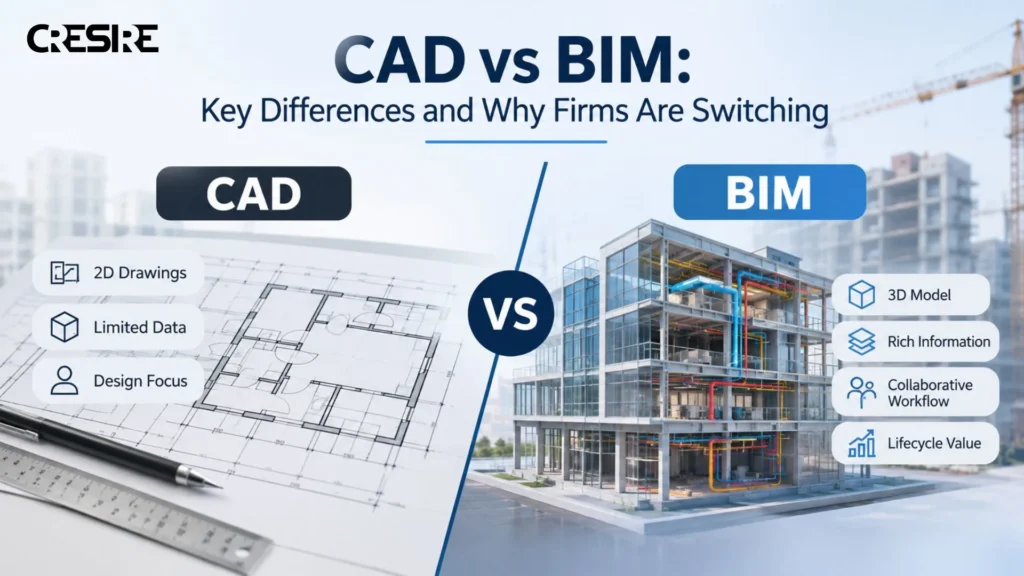
Computer-Aided Design (CAD) has played an important role in architecture and engineering for many years now. It assists architects and engineers in creating flat designs and architectural drawings. It is a helpful software application simplifying document creation and design visualization.
But times have changed. Construction projects have gotten more complicated, and it requires teams working from different locations to coordinate their work together. In addition to the drawings, constructors need the information that will be useful for everyone involved in the project, such as architects, builders, and engineers.
And it is the time when BIM comes into play.
The discussion of CAD vs BIM is no longer simply about choosing one of these two tools. It is about the approach to building design, project information management, changes making, and building construction.
It should be noted that CAD is still very much useful, as it successfully solves the task of creating drawings. But BIM introduces a management system for the information regarding the building, from its planning to its usage.
So what is the difference between BIM and CAD? Why do many engineering, construction, and architectural companies decide to implement BIM?
What Is CAD (Computer-Aided Design)?
CAD, which stands for computer-aided design, is important because it enables me to draw, alter, assess, and record drawings and design models. In the AEC industry, CAD has been greatly utilized because it allows preparation of layouts, structure details, mechanical drawings, electrical drawings, plumbing layouts, and construction documents. Instead of sketching by hand, I make use of software like AutoCAD to design proper 2D drawings and 3D models. Regular CAD drawings have features of the following:
- Lines, arcs, and polylines
- Dimensions and notes
- Layers and blocks
- Hatched areas and symbols
- Elevations and sections
- Technical data and drawing references
How CAD Works in Construction Projects
When a project uses Computer-Aided Drawing for the process. Each discipline in the project creates its drawings. The architectural department, for example, will make the drawings including the floor plan, elevation, and sectional drawings. The structural engineers will make foundation, column, beam, and reinforcement drawings, while MEP engineers will create the drawings for mechanical, electrical, and plumbing aspects of the project.
Each discipline conserves the drawings done by their own people. The drawings are transferred later on to others in the project. When a drawing has been changed, it has to be done manually. In case a major change is needed, it may affect other drawings as well.
The process is convenient if the project is not complicated.
What Is BIM (Building Information Modeling)?
The concept of Building Information Modeling, or BIM, in my opinion, means a technique of creating and processing the modeling of not only physical parts but also functional components of buildings.
Unlike drafting methods, BIM allows combining 3D images of buildings and their parts with significant data.
The particulars kept in BIM include all data connected with building components including their materials, sizes, specifications, equipment used, quantities, and other significant aspects that have to do with the construction process.
As an example, a wall in BIM may have such information as the width of the wall, materials used to construct it, fire resistance, sound insulation, and others.
Likewise, a mechanical duct may be described using such particulars as dimensions, type of duct, materials, height, connections, etc.
How BIM Works in Construction Projects
BIM employs a strategy focused on integration, while different teams of various disciplines create their models, and BIM ensures that all these models work in a unified project environment.
In case of any change in design, BIM changes the representations based on the relations between the models.
For example, in case the architectural team changes the arrangement of rooms, BIM allows for structural MEP teams to see the updated models.
Different BIM processes applicable for the project type are as follows:
- Clash detection and coordination of 3D Models
- Construction quantification
- Construction visualization
- 4D scheduling of construction
- 5D cost analysis
- Facility management information and data
- Project documentation and digital twins
Implementation of BIM technology does not guarantee absence of conflicts or errors in design or coordination issues.
CAD vs BIM: Key Differences Explained
While CAD and BIM can be used to support design in architecture and engineering, their philosophies differ.
CAD focuses on generating technical drawings and representations of geometry. BIM creates smart, information-based digital models.
The differences are listed below.
Comparison Factor | CAD | BIM |
Primary purpose | Technical drafting and design documentation | Building information creation and management |
Design approach | Primarily geometry-based | Object-based and information-rich |
Modeling | 2D drawings and 3D geometry | Intelligent 3D building models |
Project information | Mostly drawing-related information | Geometry, properties, specifications, and asset data |
Design coordination | Often requires manual coordination | Supports model-based multidisciplinary coordination |
Design changes | Related drawings may need manual revision | Associated views and schedules can update through model relationships |
Clash detection | Requires additional checking and coordination workflows | Supports automated or semi-automated model-based clash checking |
Quantity estimation | Measurements and manual extraction | Model-based quantity extraction when properly configured |
Collaboration | Drawing and file exchange | Coordinated model and information exchange |
Documentation | Separate drawing files and references | Drawings and schedules generated from model data |
Project lifecycle | Commonly focused on design and documentation | Can support design, construction, and operations |
Common software | AutoCAD, MicroStation | Revit, Archicad, Tekla Structures |

The biggest distinction is that drawings are used to convey the design in CAD, while geometry and other project information are connected in BIM, making it easier to manage throughout the development.
7 Major Differences Between CAD and BIM
This table is an introduction; however, the significance of these differences in terms of impact on the construction process must be considered when determining the approach to employ.
Drawing-Based Design vs. Model-Based Design
CAD and BIM are different in terms of representing building information.
CAD uses the drawing method to create drawings where certain objects are used in the process. This implies that CAD provides lines, dimensions, symbols, and notes to inform about building components. For instance, the architectural floor plan generated by CAD will have walls, doors, rooms, and movement areas. However, CAD does not provide information regarding the nature of these building components.
Building Information Modeling uses construction objects to provide information about building components. For instance, BIM provides information about doors, like their size, material, fire rating, and manufacturer. Other components, like columns, get information about their cross-section design and material.
Manual Drawing Updates vs. Model-Driven Documentation
I notice that changing a design in a CAD environment leads to the simultaneous updating of various drawings.
For example, when an architect moves a wall in a building, the floor plan has to be changed too. There are other drawings as well, such as the reflected ceiling plan, the plan, the furniture plan, etc, that may also require adjustments.
Failure to make appropriate updates in CAD may result in inconsistencies between drawings.
However, this situation is rare in BIM since BIM relies on model-based documentation.
Once a properly designed wall is moved, all related views and schedules are updated by the model automatically.
Nevertheless, BIM does not automatically mean that all the design decisions are made in harmony.
The engineers still have to check the system in order to comply with the project requirements and approve the changes.
What it means: the model-based documentation allows removing drafting and improving coordination between materials.
Separate Discipline Drawings vs. Multidisciplinary Coordination
Different disciplines are needed in the construction industry.
Disciplines such as architecture, structural design, mechanical design, electrical design, and plumbing will sit in the same place. Hence, it is essential to collaborate between these disciplines to avert difficulties during construction.
When using computer-aided design (CAD), teams usually exchange drawings. They will check the drawings by placing them one atop another or using some other coordination methodology.
When using building information modeling (BIM), discipline-specific models can be integrated into a huge model for better coordination.
For instance, MEP coordination can reveal:
- HVAC ducts in beam areas.
- Plumbing pipes hitting trays of cables.
- Insufficient space near the equipment.
- Ducts interfering with ceiling components.
- Insufficient space near maintenance facilities.
With modern software like Autodesk Navisworks, teams can identify conflicts before construction.
This is important because coordinating models early helps the team fix space problems in the model and on the actual site.
Geometric Information vs. Intelligent Building Data
CAD diagrams provide measurements, forms and technical relations.
BIM utilizes the CAD diagrams to introduce attributes of the building elements.
Let’s take the example of the duct in the HVAC system.
In the CAD equation, the duct is represented as lines and symbols indicating its position and dimensions only.
In the BIM equation, the duct gives more information:
- Width and height
- Classification of the system
- Material specification
- Height and position
- Airflow parameters
- Insulation properties
- Connection information
Depending upon the model and its purpose.
This phenomenon becomes very important in case the models are used for capital construction documents, quantity calculations, schedules of the equipment and facilities management.
The importance of the problem: BIM provides more possibilities of utilizing the information than simply transferring the drawings and tables.
Manual Quantity Extraction vs. Model-Based Quantities
Another point of difference between the two methods is the calculation of quantiles. In CAD, there are various ways of calculating quantities by means of measuring tools, schedules, spreadsheets, and by hand.
The estimator will need to measure the walls, calculate the areas of the floors, and count the doors and windows.
In BIM, extraction of quantities from the model can be performed.
The quality of the results will depend on the quality of the model:
- Volume of concrete
- Area of walls and floors
- Number of doors and windows
- Structural items
- Lengths of ducting
- Lengths of piping
- Equipment schedule
But these quantities should not be used as the only source for procurement and costing because there may be quantities that were not included in the model.
BIM can be a huge advantage when performing quantity take-off. If the quality is good enough, you can create an accurate estimate.
Limited Lifecycle Information vs. Connected Asset Information
Throughout the design and building phases of any project, traditional CAD documentation is generally employed.
After completion of the project, the facility manager is often burdened with the task of gathering information from several sources—some of which may include drawings, lists of equipment, and manuals for operation.
The alternative approach is to use BIM to provide an integrated and centralized source of data about buildings.
If a built and verified as-built model was developed, aspects like details about locations of equipment, systems, IDs of assets, and maintenance information could also be taken into account.
The data obtained would be useful for further operation of the building, for renovation planning and for carrying out maintenance actions.
One has to bear in mind that having a BIM model does not equal getting a digital twin of the building.
The value of BIM models depends on the information needed from the very beginning and on the degree of precision and completeness of the handover process.
Why this matters: BIM can extend the usefulness of project information beyond construction and support long-term asset management.
File-Based Exchange vs. Structured Information Exchange
CAD projects use the DXF and DWG file formats. Federated formats or open standards, including the IFC format, can be used in Building Information Modeling (BIM) projects. The IFC format is essential for transferring data between various BIM software applications. This is crucial since, in different software applications, architects, engineers, builders, and other stakeholders perform their tasks with information from BIM applications. It is vital to ensure that model information, such as elements, classifications, properties, and geometry, are exported and imported correctly. Information management processes, which will involve naming convention, document versioning, and deliverables, should be utilized.
Why this matters: Structured information exchange helps project participants coordinate across different software environments and maintain more consistent project records.
CAD vs BIM: A Practical Construction Project Example
To understand the difference more clearly, consider a commercial office building with multiple floors, structural systems, HVAC equipment, electrical installations, and plumbing networks.
Scenario 1: Project Developed Using CAD
The architecture team is responsible for preparing the floor plans, building elevations, and sections.
The structural engineers will create the structural drawings showing the foundations, beams, columns, and slab.
The MEP engineers will create the MEP drawings.
While coordinating the drawings together, the contractor will find that there is a clash between an HVAC system duct and a structural beam.
We need to find out which drawings have been affected, see how much working space we have, discuss the possible considerations for a redesign, and issue a new set of drawings.
If the changes affect various drawings, we should review all files and make any necessary alterations.
While this can be a fairly straightforward process, the increasing number of drawings and disciplines can mean increasing challenges to coordinate.
Scenario 2: Project Developed Using BIM
The Architectural, Structural, and MEP teams create models with BIM.
All models are consolidated for review by multiple disciplines.
During MEP coordination, we discover that the main HVAC duct is in conflict with a structural beam.
This conflict is resolved before construction. This is done by the MEP engineer looking at the different options for the duct and the structural engineer reviewing the solution to make sure it meets the structural needs.
The design is then approved and the relevant model and documents updated.
This information can then be passed onto the contractor to help with their planning.
It isn’t that BIM prevents conflicts but provides a framework for the project team to identify, communicate and resolve design coordination issues.
Why Are AEC Firms Switching from CAD to BIM?
This change can be attributed to changes in the requirements of projects.
Many companies find it problematic to manage projects using a traditional 2D drawing-based approach when dealing with multi-disciplinary projects which involve many changes, complex building systems and high documentation standards.
Below are some of the key reasons that have led to the adoption of BIM:
Increasing Complexity of Construction Projects
Modern commercial buildings, healthcare facilities, education and industrial developments all include complex building systems.
Managing these using individual drawings can lead to issues working together.
BIM provides a shared model-based approach with all disciplines being able to look at the design together.
Better MEP and Structural Coordination
MEP systems often have an issue with getting enough room in ceilings, service routes, shafts and plant rooms.
This can cause issues with cabling and can affect how the system is installed and affect maintenance clearances.
Using BIM to coordinate will help locate any issues beforehand.
For Contractors and Engineering Consultants, this can help with planning the build and reduce any unnecessary rework.
Improved Design Revision Management
During construction, there are often many changes due to client requirements, site conditions, design variations and regulation.
This can cause a lot of coordination when trying to manage these changes within individual CAD drawings.
Using BIM creates a more integrated documentation process that can be reviewed to see how changes affect related areas of the model from different disciplines.
Greater Visibility Before Construction
Conventional drawings are often open to interpretation by the stakeholders involved in the project. They provide information on the design layout in the form of plans, sections, elevations, and technical drawings.
BIM models allow for a 3D representation of the design, which can make complex situations easier to understand.
All parties involved (architects, contractors, engineers and owners) can have a look at how everything will fit into the space, where equipment will be located, any accessibility requirements and any potential issues during construction.
Support for Digital Construction Workflows
Many AEC companies are starting to look at using digital processes to manage their construction operations, including model coordination, quantity take-off, sequencing and asset information management.
BIM provides the platform to integrate these processes using data within a building information model.
Applications can include 4D, 5D, reality capture, digital twin and facilities management.
Increasing Client and Project Delivery Requirements
Some owners, government bodies and large construction organisations will have BIM output requirements.
This might involve a requirement for certain formats, Level of Information Need, coordination processes, naming standards, information exchange and asset data within the model.
Companies offering coordinated BIM models are in a better position to get involved in projects requiring model-based information.
CAD to BIM Conversion: A Practical Route for Existing Projects

Migrating to BIM does not require any of your CAD drawings to be lost.
Many AEC firms will have large amounts of architectural, structural and MEP drawings which are still very useful.
These can be used as a base to help you convert to BIM from CAD.
This involves creating a structured 3D BIM model from 2D CAD drawings.
A typical CAD to BIM workflow would consist of:
Step 1: Review Existing CAD Drawings
First, we will evaluate the drawings we have.
Architecture plans, sections and elevations, structural details and MEP drawings.
We will check how accurate the drawings are, what scale they’re on, if there is any missing information, and also how organised the layers are. We will also check that all the drawings are consistent across all sets.
Step 2: Prepare and Organize Drawing Data
The process will start by getting CAD files organized by removing extra layers, duplicated geometry, referencing mistakes, or inconsistencies in drawings.
Step 3: Establish the BIM Modeling Standards
Then, the modeling team determines the software that is required, project coordinates, levels, grids, nomenclature standards, family standards, and information needs.
The appropriate Level of Development (LOD) or Level of Information Need is established according to the intended deliverables.
Step 4: Develop the 3D BIM Model
CAD references will be used to create building elements as BIM objects.
This can consist of walls, floors, doors, windows, columns, beams, ducts, pipes, cable trays and many others depending on the project scope.
The model should not be a replica of the original drawing but should represent the real requirements of the project.
Step 5: Perform Model Validation and Quality Checks
The model has been checked against the drawings and any information available.
Quality checks can include:
- Correct dimensions
- Correct orientation
- Correct level/grid
- Correct categorisation of elements in the model
- Correct properties for components
- Completeness of geometry
- Correct coordination between disciplines
Step 6: Deliver the BIM Model and Documentation
Final deliverables will be created according to the agreed requirements.
This can include native Revit files, IFC files, co-ordinated models, drawings, schedules and other documentation.
In renovation projects or where there is an existing building, additional verification on site or laser scanning may be required due to not all CAD drawings being accurate to the site.
Can CAD and BIM Be Used Together?
Correct. Many AEC companies will use CAD in their practice.
They are not an either/or situation.
CAD can be used to produce detailed drawings, update previous drawings, produce 2D detailing, and coordinate with any consultants who use CAD.
BIM is better suited for projects where there is a need for integrated 3D modelling, coordination and structured building information.
An Architectural Engineering company may get DWG’s from their client which they can use as a baseline to produce a Revit model. From here, they can coordinate between Architectural, Structural, and MEP.
However, it may be required to export DWG’s at the end of the project.
This means that they can use the existing drawings and gradually transition into an integrated environment.
CAD vs BIM: Which One Should Your Firm Choose?
Depending on the complexity of the project, client requirements, resources, and deliverable requirements, you should consider which option to use.
When CAD Is the Right Choice
There is no ‘best’ solution for all circumstances.
CAD can be a more practical option if:
- The project is largely 2D in nature.
- The project is small scale, such as renovation or drawing amendments.
- There is existing documentation in DWG format.
- The client wants CAD deliverables.
- Multi-discipline collaboration in 3D is not needed.
When BIM Is the Better Choice
There is little modelling and information requirements in the project.
BIM will generally be a more suitable option if:
- There are multiple disciplines of design.
- Architectural, structural and MEP coordination is required.
- The building is complex with complex systems.
- Quantity take-off is to be done using the model.
- The client wants coordinated 3D models.
- Construction planning and clash detection are key.
- Structured information about assets is required.
Challenges Firms Should Consider Before Moving from CAD to BIM
Whilst there are many benefits of using BIM, consideration should be taken when moving away from CAD.
Training & Knowledge: Teams will need to have a good understanding of BIM modelling, how to follow project standards, what information is required and how to coordinate. Teams will already know about CAD, but further training will be needed.
Investment in Software & Hardware: Appropriate hardware, software (subscription), collaboration tools and data management tools may be needed.
Consistency: If there is no consistency with naming standards, model structure, families and documentation, it can cause problems with BIM projects.
Poor quality existing drawings: Current CAD drawings may not be up-to-date, missing information, or inaccurate. This should be identified beforehand.
Coordination: BIM requires coordination across disciplines. All teams should know what they are responsible for, what information they need to provide, how to manage changes, and how they need to exchange models.
Validation: Just because a model looks complete doesn’t mean it is accurate or has good information. Validation should be done properly before models are used for construction or facilities management.
By considering these requirements early on, firms can save unnecessary costs and get more value out of their BIM investment.
The Future of CAD and BIM in the AEC Industry
The future of digital design and construction is a move towards a more efficient way of producing, co-ordinating, sharing and managing project information.
BIM is continuing to develop by integrating with other digital design and construction technologies such as reality capture, cloud collaboration, digital twins, computational design, etc.
Using technologies like laser scanning allows real-world conditions to be captured in the form of point clouds. These point cloud datasets can be used to create accurate BIM models for as-built projects such as renovations, retrofits, and facility management.
Digital twin processes allow building information to be linked to operational data.
OpenBIM initiatives and using IFC formats to share information are improving collaboration across various platforms.
Whilst CAD will still play a part in technical drawing, due to increased requirements in project information, BIM is becoming a more integral part of modern AEC project delivery.
Adopting BIM will give your firm the strategic advantage to increase co-ordination, handle complexity within your designs and provide more useful project information.
Frequently Asked Questions About CAD vs BIM
What is the main difference between CAD and BIM?
The main difference is how design information is created and managed. CAD focuses primarily on producing 2D drawings and 3D geometric representations, while BIM uses intelligent building objects that combine geometry with information such as materials, dimensions, specifications, and other project data.
Is BIM better than CAD?
BIM is generally more suitable for complex projects requiring multidisciplinary coordination, model-based documentation, and structured building information. CAD remains effective for 2D drafting, technical details, and projects with straightforward documentation requirements. The better choice depends on the project scope.
Can CAD drawings be converted into BIM models?
Yes. Existing DWG and DXF drawings can be used as references for developing 3D BIM models. The conversion process typically involves drawing assessment, reference preparation, modeling, information assignment, and quality validation.
Is AutoCAD considered BIM software?
No. AutoCAD is primarily CAD software used for 2D drafting and 3D design. It can support BIM-related workflows by producing and exchanging drawings, but it is not a dedicated BIM authoring platform like Autodesk Revit.
What is the difference between AutoCAD and Revit?
AutoCAD is primarily designed for creating and editing technical drawings and geometric models. Revit is a BIM authoring platform that allows users to develop information-rich building models containing architectural, structural, and MEP components.
Does BIM eliminate the need for CAD drawings?
No. BIM does not eliminate the need for technical drawings. Construction documentation is still an important project deliverable. BIM software can generate coordinated 2D drawings and schedules from the model, while CAD remains useful for detailed drafting and drawing exchange.
How does BIM improve MEP coordination?
BIM allows mechanical, electrical, and plumbing models to be reviewed together with architectural and structural models. This helps project teams identify spatial conflicts, evaluate equipment clearances, coordinate routing, and resolve design issues before construction.
What is CAD to BIM conversion?
CAD to BIM conversion is the process of transforming existing 2D CAD drawings into structured 3D BIM models. It involves creating building elements, assigning relevant properties, establishing model standards, and validating the resulting model against available project information.
What is the role of LOD in BIM?
Level of Development (LOD) describes the reliability and development of model elements at different project stages. LOD 100 through LOD 500 represents increasing levels of model development and information. The required LOD should be defined according to project deliverables and intended model uses.
Which industries benefit most from BIM?
Architecture, structural engineering, mechanical engineering, electrical engineering, plumbing, general contracting, infrastructure, healthcare construction, industrial facilities, and facility management can all benefit from BIM when project requirements justify its use.
Final Thoughts
The comparison between CAD and BIM highlights an important shift in the AEC industry: moving from drawing-focused design processes toward more integrated and information-driven project delivery.
CAD remains an important technology for technical drafting, detailed documentation, and existing drawing management. BIM builds on these capabilities by connecting building geometry with structured information and supporting collaboration across project disciplines.
For architectural and engineering firms managing increasingly complex projects, the decision to adopt BIM is about more than improving visualization. It is about strengthening coordination, maintaining consistent project information, and supporting better decisions throughout the building lifecycle.
Whether a firm is starting a new BIM project or transitioning existing CAD documentation into intelligent 3D models, a well-planned workflow can make the transition more practical and effective.
Looking to move from traditional CAD drawings to coordinated BIM models? Cresire supports AEC projects with BIM modeling, CAD to BIM conversion, architectural and structural modeling, MEP BIM coordination, and Scan-to-BIM solutions. Our team helps project stakeholders develop accurate, coordinated digital building information based on their project requirements.
NDA available