

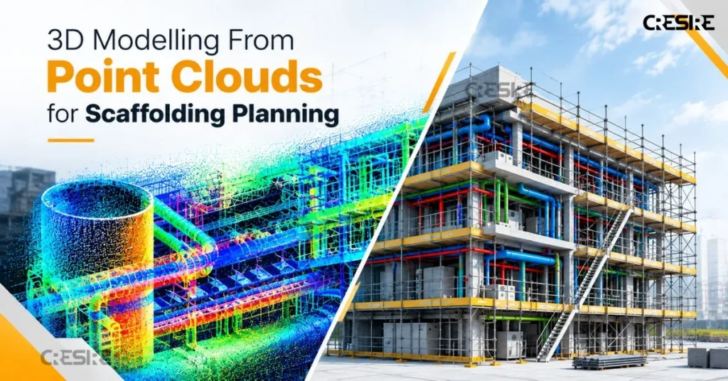
Planning scaffolding on a straightforward commercial façade is one thing. Planning it around a chemical plant, processing facility, conveyor system or heavily congested industrial site is very different.
The drawings may show the building, but they may not fully show what is actually there today. A site may have additional pipework, platforms, equipment, structural modifications, access restrictions or temporary installations that make scaffold planning more complicated than it initially appears.
This is where a 3D model developed from point cloud data can become useful.
Instead of asking a scaffold designer to interpret a large point cloud or rely on disconnected 2D drawings and site measurements, the relevant site conditions can be developed into a structured Revit or IFC model. The model provides a more practical digital representation of the environment around which the scaffold needs to be planned.
For Australian scaffolding companies working on commercial, industrial, maintenance and refurbishment projects, this can make the transition from site information to scaffold planning considerably easier.
Why Scaffolding Planning Gets Difficult on Existing Sites
The challenge is rarely the scaffold itself.
The difficulty is fitting the scaffold around everything that is already there.
On an industrial site, a scaffold designer may have to work around:
- Silo tanks and vessels
- Pipework and services
- Structural steel
- Access platforms and walkways
- Conveyor galleries
- Stairs and ladders
- Equipment and machinery
- Cranes
- Building façades
- Roof structures
- Existing temporary works
- Restricted access areas
Even when drawings are available, there can be a gap between what the drawings say and what the site actually looks like.
This becomes particularly important on older facilities or sites that have been modified over several years. Original drawings may not reflect later additions, relocated equipment or changes to services.
A scaffold that appears straightforward on a drawing can therefore become difficult to erect once the team reaches site.
Australian scaffolding work also sits within a broader WHS framework where risks associated with scaffolds need to be identified, assessed and controlled. Safe Work Australia identifies hazards including falls, scaffold collapse, falling objects and electrical risks, and requires appropriate risk-management processes for scaffolding work.
A good digital site model does not replace engineering or safety processes, but it can give the project team better information before physical work begins.
What Does Point Cloud to 3D Modelling Mean for Scaffolding?
A point cloud is essentially the digital record of the scanned environment. It can contain millions or billions of points representing surfaces and objects captured during a laser survey.
But a point cloud is not necessarily the most practical format for every member of a project team.
For a scaffolding application, the relevant information can be interpreted and developed into a structured 3D BIM for Scaffolding.
The workflow is broadly:

Existing Site → Laser Scan → Point Cloud → 3D Model → Scaffold Planning
CRESIRE works on the modelling part of this process.
If your surveyor or scanning company has already captured the site, the resulting RCP, RCS, E57, LAS, PTS or PTX data can be provided for modelling.
The required building and site elements can then be developed into a Revit or IFC model according to the project’s intended use.
This is particularly useful when the scaffolding team does not need a complete BIM model of every asset on the site. The model can instead focus on the structures and obstructions that matter to the scaffold.
What Problems Can a 3D Site Model Help Solve?
1. The drawings don't match the site

This is one of the most common problems with existing buildings.
A set of architectural or structural drawings may be available, but they may have been prepared years earlier. Since then, equipment may have been added, services relocated, platforms modified or structures extended.
A scan-derived model provides a current representation of the captured site conditions.
The purpose is not to assume that the model is automatically perfect. The source scan still needs to be reviewed for coverage, registration quality and areas that may be hidden from the scanner.
But it gives the design team a much stronger starting point than relying entirely on outdated documentation.
2. There are too many obstructions to understand from 2D drawings
Consider a scaffold being planned around an industrial vessel.
The scaffold may need to pass around platforms, pipework, structural members and access points at several elevations.
On separate 2D drawings, these elements may appear on different plans, sections and elevations.
In a 3D environment, their spatial relationship becomes much easier to understand.
The designer can see where the vessel sits relative to the platform, how far an obstruction projects and where available working space may be limited.
That does not automatically produce the scaffold design. It provides a better existing-condition model around which the scaffold can be designed.
3. Site measurements are difficult or time-consuming

Some areas of an industrial site are simply difficult to measure repeatedly.
There may be restricted access, operating equipment, elevated structures or areas that cannot easily be reached during normal site activities.
If a registered point cloud already exists, the relevant geometry can be extracted from the captured information without requiring every dimension to be manually collected again.
This can be especially valuable when a scaffold designer is working remotely from the site.
4. Scaffold positioning needs to be coordinated with other work

Scaffolding can interact with much more than the building envelope.
A proposed arrangement may need to account for:
- Existing equipment
- Pipework
- Mechanical services
- Electrical services
- Access routes
- Crane operations
- Material movement
- Maintenance areas
- Other temporary works
A structured revit model from point cloud gives these elements a common spatial reference.
That makes it easier for different project participants to discuss the same condition rather than interpreting separate drawings independently.
For example, an aerial view may be appropriate for a large multifamily or mixed-use development where site relationships are important.
A street-level perspective may be more useful for evaluating a commercial building’s façade and entrance.
The principle is simple: Choose the camera angle based on what the viewer needs to understand, not simply on what makes the building look dramatic.
What Makes a 3D Model Useful for Scaffolding Planning?
A 3D model is only useful to a scaffolding team if it helps answer practical site questions.
The objective is not to reproduce every object captured by the laser scanner. It is to give the scaffold designer a reliable understanding of the geometry, levels, access conditions and surrounding constraints that could influence the proposed scaffold.
For example, when planning around an existing structure, the model should make it easier to understand:
- Where the existing structure actually sits– including its shape, levels, projections and changes in geometry.
- What is around the structure– such as platforms, pipework, equipment, conveyors or other obstructions.
- How different elements relate spatially– particularly where several structures overlap or occupy different elevations.
- Where access may be restricted – including narrow areas, elevated platforms and congested sections of the site.
- Where clearances need closer attention– especially around equipment, services, structural members and access routes.
- Which areas need detailed review– allowing the scaffold team to focus on locations where installation or access could become difficult.
This is where modelling decisions become important. A highly detailed model is not automatically a better model for scaffolding. If unnecessary elements make the model difficult to navigate without contributing to the planning process, the additional detail may provide little practical value.
The better approach is to define the intended use of the model first, then determine what needs to be modelled and at what level of detail.
For a simple commercial façade, that may mean accurate building geometry, openings, projections and surrounding conditions.
For a chemical or processing facility, the requirement may be considerably broader because scaffold planning can depend on the relationship between tanks, platforms, galleries, conveyors, structural steel, pipework and equipment.
The best scaffolding model is therefore not the model with the most objects. It is the model that gives the planning team the right information to make decisions about the site.
Why Revit or IFC Can Be More Useful Than a Raw Point Cloud

A point cloud is extremely valuable source information, but not every project participant wants to work directly inside a large scan dataset.
A Revit or IFC model can provide a more structured representation of the relevant site.
For example, a scaffold designer may want to:
- isolate specific elements;
- view the building from different angles;
- review sections;
- understand levels;
- reference structural geometry;
- coordinate with other models;
- use the model in a broader BIM environment.
The exact workflow depends on the software being used by the scaffolding company.
This is why Revit and IFC deliverables can be useful when the scaffold team needs a model rather than simply access to the original scan.
The model can also be developed alongside existing architectural, structural or MEP information where the project requires it.
A Practical Industrial Example
Imagine a chemical or processing facility where scaffolding is required around a group of silo tanks.
The area contains:
- multiple silo tanks;
- lower and upper access platforms;
- walkways;
- an overcell gallery;
- an undercell gallery;
- an inclined conveyor gallery;
- structural steel;
- pipework;
- a tower crane; and
- a workhouse structure.
The challenge is not simply determining the location of the silos. The scaffold designer needs to understand the relationship between all these elements.
Where does the platform project from the silo?
How much space exists between the gallery and the structure?
What is behind the conveyor?
Where does the structural steel interfere with the proposed scaffold?
Which areas need to remain clear for equipment or site operations?
Trying to answer all of these questions from disconnected drawings can take considerable interpretation. A point-cloud-derived 3D model brings the relevant geometry into one environment. The scaffold designer can then use that model as the existing-condition reference for their own planning and engineering process.
This type of digital workflow is already emerging in Australia’s scaffolding sector. Layher Australia, for example, describes the use of 3D point-cloud scanning to design around complex existing industrial structures and identify potential clashes before construction
Where 3D Modelling Can Improve Site Execution
The value of a model is not limited to the design office.
A well-prepared model can also help project teams communicate what has been planned before the scaffold arrives on site.

Teams can review the proposed work area, existing conditions and access constraints.
Scaffold requirements can be discussed alongside architectural, structural, MEP or industrial information.
Potential problem areas can be identified and discussed before workers and materials arrive on site.
3D views and drawings can provide an easier visual reference for understanding the existing environment.
This aligns with the broader direction of digital scaffolding planning in Australia. Industry solutions are increasingly using 3D models to support planning, coordination and implementation rather than treating digital modelling as purely a presentation exercise.
When Should a Scaffolding Company Consider Point Cloud-Based 3D Modelling?
It can make sense when:
- Existing drawings are incomplete or outdated
- The site has undergone significant modifications
- The scaffold needs to work around complex equipment
- The project involves industrial or chemical facilities
- There are multiple levels of platforms and access structures
- The site contains conveyors or galleries
- Manual measurement is difficult
- The survey has already been completed
- The project team needs Revit or IFC rather than raw scan data
- 2D plans, sections or elevations need to be produced from current site information
- Multiple stakeholders need a common view of the existing conditions
It is not necessarily required for every scaffolding project.
For a simple, well-documented building, conventional drawings may be sufficient.
The strongest case for scan-derived modelling is where existing conditions are complicated enough that uncertainty starts affecting planning, coordination or execution.
The Real Benefit: Less Guesswork Before the Scaffold Reaches Site
The biggest advantage of a point-cloud-derived 3D model is not that it makes scaffolding “digital.”
It is that it can reduce uncertainty.
A scaffold designer can see the relationship between the building and the surrounding environment before the team starts erecting the structure. A contractor can communicate difficult site conditions more clearly. Engineering teams can coordinate against a common spatial reference. And project managers can identify potential issues earlier in the process.
For straightforward projects, this may not justify the additional modelling effort.
For a congested industrial facility with silos, platforms, pipework, galleries, conveyors, cranes and multiple levels of access, the difference can be substantial.
The point cloud captures the site.
The 3D model makes that information easier to work with.
Final Thoughts
Scaffolding planning is becoming increasingly digital, particularly on complex industrial and commercial projects.
But the useful part is not simply having a laser scan.
The real value comes from turning that scan into information that the project team can actually use.
For scaffolding companies, that may mean developing a Revit or IFC model of the relevant existing structures, producing 2D drawings from the point cloud, or creating a coordinated digital reference for scaffold planning and site execution.
If your survey team has already captured the site, you do not necessarily need another scanning service. The existing point cloud can become the starting point for a structured 3D model tailored to your scaffolding requirements.
Have a point cloud from an Australian scaffolding project? CRESIRE can convert the scan data into Revit, IFC or 2D CAD deliverables based on your project requirements.
Frequently Asked Questions - FAQs
Can you create a Revit model from our existing point cloud?
Yes. If you already have registered point cloud data, it can be used as the reference for developing a Revit model according to the agreed modelling scope.
Can an IFC model be created from point cloud data?
Yes. IFC can be provided where it is the required project exchange format.
Can point cloud data also be used to create 2D scaffolding drawings?
Yes. Plans, sections, elevations and other CAD documentation can be developed from point cloud data according to the project requirements.
Do we need to model the entire industrial facility?
No. The model can be limited to the structures, equipment and areas that are relevant to the scaffolding requirement.
Can you model silo tanks, platforms and conveyor galleries?
Yes, provided the relevant elements are captured adequately in the point cloud and included within the agreed modelling scope.
Does a 3D model replace scaffold engineering?
No. The model provides an existing-condition digital reference. Scaffold engineering, structural calculations, design decisions and certification remain the responsibility of the appropriately qualified professionals
Do you provide the laser scanning?
CRESIRE’s role is primarily the modelling and drawing production stage. You can provide point cloud data captured by your own surveyor or scanning provider, and we can develop the required 3D model or 2D drawings from it.
NDA available