

IN THIS BLOG
SHARE

A structural design can be technically sound and still create problems when it meets the rest of the building.
A beam may satisfy its engineering requirements but reduce the space available for mechanical services. A column location may interfere with an architectural opening. A slab penetration introduced later for MEP services may require another structural review. Even a relatively small change in floor levels can affect several disciplines at once.
These are not unusual situations. They are part of designing buildings where architecture, structure, and building services must eventually occupy the same physical space.
This is where BIM for structural engineering has changed the way structural information is developed and communicated.
When we use BIM we do not have to look at drawings as something that stands alone. BIM lets us put beams, columns, slabs, foundations, structural walls, framing and openings together in one digital space.
This way structural engineers can see their design, in three dimensions, which’s really helpful. At the time architects and MEP teams can see how the decisions that structural engineers make will affect their own work with BIM.
The value isn’t simply a better-looking structural model.
It is having structural information that can be understood, reviewed, coordinated, and developed throughout the project.
What Does BIM Mean for Structural Engineering?
For engineers BIM is really a different way of organizing building information.
Traditional structural documentation uses plans, sections, schedules, details, notes and specifications. These are still important in a BIM workflow. The information can now come from a model that is all connected instead of from drawings that are mostly separate.
A structural column in a BIM model is not just a rectangle drawn on plans. It has a place in the building, a certain height, a specific shape, a type of material, how it connects to different levels and other details based on what the project needs.
The same idea is true, for beams, slabs, foundations, structural walls and framing systems.
This creates an important relationship:
Change the model, and the consequences of that change become easier to understand across multiple views and disciplines.
That is one reason BIM for structural engineering has become increasingly important on multidisciplinary projects. Structural engineers aren’t only communicating what needs to be built; they are contributing information to a wider digital representation of the building.
Where Revit Fits Into Structural BIM
Autodesk Revit is one of the most widely used BIM authoring platforms for building projects and provides dedicated tools for structural modeling and documentation.
Using Revit for structural engineering, teams can develop structural elements within the same spatial framework used by architectural and MEP disciplines.
Depending on the project scope, a structural Revit model may contain:
- structural columns;
- beams and framing;
- concrete slabs;
- structural walls;
- isolated and continuous foundations;
- pile caps and other foundation elements;
- trusses;
- structural openings;
- stairs and associated structural components;
- reinforcement information where required.
The advantage isn’t that Revit simply makes these elements three-dimensional.
It is that they can be developed relative to grids, levels, architectural geometry, openings, and other project information.
That makes the structural model much more useful for multidisciplinary review.

How BIM Changes the Structural Design Workflow
The transition from conventional structural drafting to BIM doesn’t mean engineering judgement moves into the software.
The calculations, design assumptions, loading criteria, codes, and engineering decisions still belong to the structural engineer.
What changes is the environment in which those decisions are represented and coordinated.
A typical structural BIM workflow can be understood in several stages.
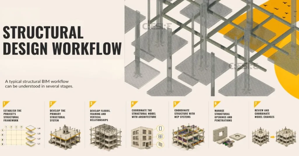
Step 1: Establish the Project's Structural Framework
Before detailed modeling begins, the team needs a reliable project framework.
Architectural models or drawings are reviewed to understand building geometry, floor levels, grids, cores, walls, major openings, and other design constraints.
Structural grids and levels can then be established according to the agreed project information.
This stage deserves more attention than it sometimes receives.
If the architect and structural engineer are working with different grids, levels, or coordinates, the discrepancy will eventually appear somewhere else in the project. Starting from a common spatial reference gives subsequent structural design coordination a much stronger foundation.
Step 2: Develop the Primary Structural System
Once the framework is established, the major structural components can be developed.
Depending on the building and structural system, this may include foundations, columns, structural walls, beams, slabs, braces, and roof framing.
The required Level of Development should be considered from the beginning.
An early design model may only need to communicate the general structural system and approximate geometry. A model being developed for detailed coordination or construction will typically require greater definition.
This distinction matters because adding detail without a clear project purpose creates additional modeling effort without necessarily creating additional value.
Step 3: Develop Floors, Framing and Vertical Relationships
Structural systems rarely make sense when viewed one floor at a time.
Columns continue between levels. Beams support slabs and other framing. Transfer structures may redistribute loads. Roof framing can introduce different slopes and elevations. Foundations relate back to the vertical structure above.
Developing these elements within a 3D BIM environment makes their relationships much easier to review.
Sections through the model can reveal conditions that may not be immediately obvious from a structural plan alone.
This is particularly useful around transfer zones, changes in floor levels, complex roofs, cores, and other areas where the structural geometry becomes less repetitive.
Step 4: Coordinate the Structural Model With Architecture
This is where structural BIM starts becoming a multidisciplinary process.
A structural model may work perfectly well in isolation and still conflict with the architectural design.
Columns need to be checked against walls, doors, glazing, and room layouts. Structural slab edges need to correspond with the building envelope. Beams may affect ceiling heights or architectural openings. Structural walls need to work with circulation and spatial requirements.
Consider a beam running above a corridor.
From a structural perspective, its depth may be entirely appropriate. But if the architectural design requires a particular ceiling height and MEP services also need to pass through the same zone, that beam depth becomes a multidisciplinary consideration.
Structural design coordination makes these relationships visible before they become site constraints.
Step 5: Coordinate Structure With MEP Systems
MEP coordination is often where structural BIM delivers some of its clearest practical value.
Mechanical ducts, plumbing pipes, electrical containment, and fire protection systems frequently need to pass through or around structural zones.
A typical coordination review might identify:
- ducts intersecting beams;
- pipes crossing structural columns;
- service risers conflicting with slabs;
- openings missing from structural walls;
- equipment requiring additional structural support;
- drainage routes affected by beam depths;
- MEP penetrations requiring structural review.
Clash detection can help identify these intersections, but software cannot determine the correct engineering response.
A duct passing through a beam does not automatically mean the beam should be modified. The MEP route may need to change. The duct size might need reconsideration. A penetration might be possible, but only after structural assessment.
The model identifies the interface.
The engineers decide how it should be resolved.
That distinction is fundamental to good BIM coordination.
Step 6: Manage Structural Openings and Penetrations
Openings deserve particular attention because they sit directly at the interface between structural and MEP design.
Mechanical and electrical teams may require penetrations through slabs, beams, or structural walls. Those requirements need to be communicated early enough for the structural engineer to assess their location, dimensions, and impact.
In a coordinated BIM workflow, proposed openings can be reviewed spatially before construction documentation is finalized.
This can help teams distinguish between planned penetrations and unexpected site modifications.
For contractors, that difference can be significant.
Finding out before concrete is poured that a major service needs a slab opening is very different from finding out afterwards.
Step 7: Review and Coordinate Model Changes
Design development is rarely linear.
Architectural layouts change. Equipment gets relocated. MEP routes evolve. Structural member sizes may change as engineering progresses.
The challenge isn’t simply making a revision.
It is understanding what else that revision affects.
If a column moves, does the architectural layout still work? If a beam becomes deeper, is the coordinated MEP route still possible? If an opening gets larger, does it need another structural review?
BIM provides a common environment in which these consequences can be identified and communicated more clearly.
That does not eliminate coordination meetings or design reviews.
It makes those conversations better informed.
BIM Structural Modeling Is More Than 3D Geometry
A common misconception is that a structural BIM model is simply a three-dimensional version of structural drawings.
That misses much of its value.
A useful BIM structural model combines geometry with structured project information.
Depending on the project requirements and LOD, structural elements may contain information relating to section sizes, materials, levels, element identification, classification, and other parameters.
That information can then support schedules, quantities, documentation, coordination, and downstream project workflows.
The model therefore becomes more than a visual reference.
It becomes a structured source of structural project information.

Revit Structural Design and Engineering Analysis Are Different Things
There is also an important distinction between developing a structural model and performing structural engineering analysis.
Revit structural design workflows can represent structural systems and support coordination and documentation. Structural analysis and engineering calculations, however, require appropriate engineering methodologies, design codes, loading assumptions, and specialist analysis tools where applicable.
BIM should not blur that responsibility.
A visually convincing structural model does not prove that a structure has been engineered correctly.
The structural engineer remains responsible for determining whether member sizes, reinforcement, connections, foundations, and other structural components satisfy the relevant engineering requirements.
Revit helps represent and communicate those decisions within the BIM environment.
That distinction is especially important when structural BIM modeling is outsourced.
Project teams should establish clearly whether the BIM provider is modeling engineer-issued design information, supporting design development, performing coordination, producing documentation, or carrying an engineering design responsibility.
Those scopes should never be assumed to mean the same thing.
Structural Detailing in Revit: When Does More Detail Add Value?
As projects move toward later stages, structural models may need additional information.
Structural detailing in Revit can involve developing more detailed structural geometry, reinforcement, connections, embeds, openings, or other elements depending on the project’s requirements.
But detail should always have a purpose.
Modeling every possible component at an early design stage may make the model unnecessarily heavy and difficult to manage. At construction or fabrication stages, however, additional detail may be necessary to support the required deliverables.
The question should therefore not be:
“How much can we model?”
It should be:
“What information does the project need from the model at this stage?”
That approach keeps structural BIM practical rather than turning model complexity into a goal of its own.
Where BIM for Structural Engineering Adds the Most Value
The benefits of structural BIM vary depending on project complexity, team structure, and delivery method.
On relatively straightforward buildings, the advantages may come primarily from coordinated documentation and model-based communication.
On complex multidisciplinary projects, the impact can be much greater.
Structural grids, façade requirements, architectural layouts, and extensive MEP services need to work together. BIM helps teams review these relationships throughout design development.
Factories, warehouses, manufacturing facilities, and process buildings may contain large structural spans, equipment loads, utility routes, and complex MEP infrastructure.
A coordinated structural model can help teams understand how these systems interact spatially.
Data centers are particularly services-intensive.
Large electrical and mechanical systems, equipment support requirements, containment, pipework, and structural framing can create highly congested coordination zones.
Structural BIM allows these interfaces to be considered alongside the wider MEP coordination process.
Hospitals and laboratories often contain dense building services and numerous penetrations.
Coordinating structural elements with MEP requirements before construction becomes particularly valuable in these environments.
Stations, terminals, airports, large public buildings, and other complex facilities may involve several consultants and specialist contractors.
A shared BIM environment gives those teams a clearer way to communicate structural information within the wider project.
What Does Structural BIM Mean for Contractors?
Structural BIM is not only useful during design.
As the project moves toward construction, coordinated structural information can support constructability discussions, sequencing, quantities, openings coordination, and communication with specialist trades.
A contractor can use the model to better understand how the structure relates to architecture and building services.
For example, rather than reviewing a slab plan and MEP penetration drawing independently, the team can inspect the relationship spatially.
The same principle applies to congested ceiling zones, plant areas, equipment supports, roof framing, and complex structural interfaces.
The model doesn’t replace construction drawings or contractual documentation.
It provides another way to understand them.
BIM Does Not Replace Structural Engineering
It is easy to talk about BIM as though the technology itself solves coordination problems.
It doesn’t.
BIM gives structural engineers and project teams a better environment for seeing the consequences of their decisions.
It can reveal that a beam and duct want the same space. It can show that an architectural opening and structural column do not agree. It can help teams understand where penetrations are required before construction.
But somebody still needs to make the engineering decision.
That is why the strongest use of BIM for structural engineering is not automation for its own sake.
It is better-informed collaboration between the people responsible for designing and constructing the building.

Final Thoughts
Structural engineering has always depended on understanding relationships: loads moving through a building, beams meeting columns, slabs connecting to walls, and foundations transferring forces into the ground.
BIM adds another set of relationships to that picture.
How does the structure affect architecture? Where do MEP systems need to pass through it? What happens to other disciplines when structural geometry changes? Are openings being considered early enough? Can everyone understand the same design information?
BIM for structural engineering helps make those relationships easier to see, coordinate, and communicate.
Revit provides the modeling environment, but the real value comes from how project teams use the information within it.
A successful structural BIM model is therefore not simply one that looks complete in 3D.
It is one that helps architects, structural engineers, MEP teams, contractors, and project owners make better-informed decisions before those decisions become construction problems.
How CRESIRE Supports Structural BIM and Revit Modeling
At CRESIRE, we support structural engineering consultants, architects, contractors, and AEC companies with structural BIM modeling and Revit-based project delivery.
Our teams develop structural Revit models from client-provided engineering drawings, design information, CAD documentation, markups, and other project inputs. Depending on the scope, models can include foundations, columns, beams, slabs, structural walls, framing, openings, and other structural elements developed to the required LOD and project standards.
Where multidisciplinary BIM coordination forms part of the requirement, structural models can also be reviewed alongside architectural and MEP information to identify design interfaces and support coordinated project delivery.
Our focus is not simply on producing 3D geometry. It is on developing structured BIM information that is useful for the stage of the project it is intended to support.
For structural BIM modeling and Revit project requirements:
Email: enquiry@cresireconsulting.com
Website: www.cresireconsulting.com
NDA available