

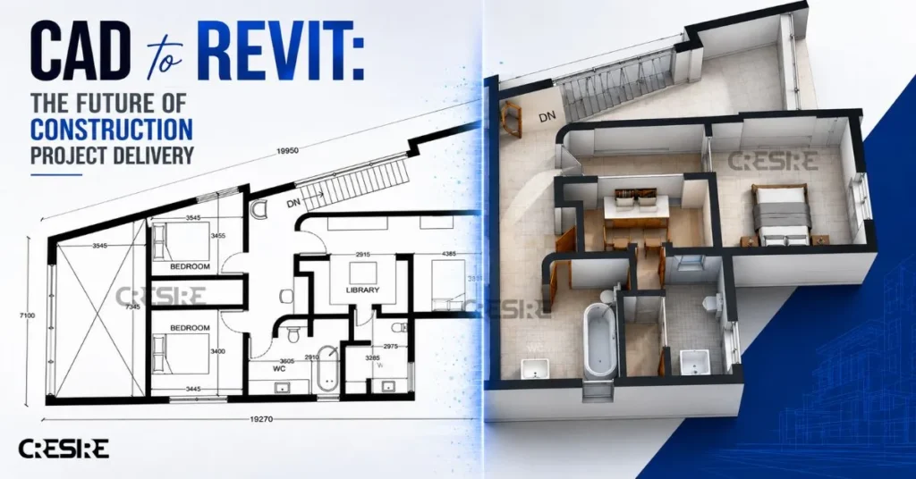
There is nothing inherently wrong with working in CAD. For many projects, 2D drawings still do exactly what they are supposed to do.
The difficulty usually appears when the project moves beyond documentation.
An architect may need to understand how a proposed design interacts with the structure. An MEP engineer needs to know whether there is actually enough space above the ceiling for ductwork and cable containment. A contractor may need coordinated information before installation begins. Suddenly, reading architecture, structure and building services from separate drawings becomes a much more demanding exercise.
This is where CAD to Revit conversion starts to make practical sense.
The objective isn’t simply to redraw a DWG file in three dimensions. It is to interpret the information contained across plans, elevations, sections, schedules and details, then rebuild that information as a structured BIM model that can support the next stage of the project.
And there is an important difference between the two.
What Actually Changes When CAD Becomes Revit?
Take something as simple as a wall.
In a CAD floor plan, the wall might be represented by lines, hatches and annotations. An experienced architect understands what those graphics mean by looking at the plan alongside sections and details.
In Revit, that same wall can become an actual building element with a defined height, thickness, type, material and relationship with floors, doors, windows and adjacent spaces.
The same principle applies across other disciplines.
Lines representing structural framing become beams and columns. Mechanical layouts can become ducts, equipment and air terminals. Plumbing drawings can be interpreted into pipe systems. Electrical documentation can inform lighting, equipment and containment models.
This is why CAD to bim conversion is better understood as information reconstruction rather than file conversion.
The DWG provides the source information. Revit provides an environment in which that information can be structured, related and eventually coordinated.
Why Convert CAD Drawings in the First Place?
Not every CAD project needs to become BIM. That’s worth saying because converting drawings simply for the sake of having a 3D model adds little value.
The transition becomes useful when the project team needs to do something that is difficult to manage efficiently through disconnected 2D information.
Consider a commercial refurbishment where the architect has one drawing package, the structural consultant another and each MEP discipline maintains its own drawings. Looking at any individual plan may not reveal a problem.
Overlay those disciplines in three dimensions, however, and the situation can look very different.
A large supply duct may occupy the same zone as a structural beam. A drainage route may not have enough vertical space to maintain the required fall. Electrical containment might compete with mechanical services above a corridor ceiling.
None of these issues necessarily means the original CAD drawings were poorly produced.
The information simply wasn’t being viewed together.
A coordinated BIM environment gives teams another way to interrogate that information before those relationships become construction problems.
From DWG to BIM: What the Process Really Looks Like
A good CAD to Revit workflow doesn’t begin with modeling.
It begins with reading.
Before developing geometry, the BIM team needs to understand what has actually been provided. Floor plans may come from one design stage, structural drawings from another, and MEP layouts from a later revision. Drawing references, units, grids, levels and coordinates all need checking before they become the foundation of a model.
Autodesk itself recommends checking and cleaning DWG files before linking them into Revit and generally recommends linking rather than importing when the CAD information may continue to change. Linked files can be reloaded as the source is updated, whereas imported CAD does not maintain that same connection.
Once that groundwork is complete, the conversion can begin.

Step 1: Review and Prepare the CAD Drawings
The first task is to bring some order to the drawing package.
Architectural plans, sections and elevations are reviewed together. Structural plans are checked against grids and floor levels. MEP layouts, reflected ceiling plans, schedules and details are organized by discipline and revision.
This is also where discrepancies start appearing.
Perhaps the structural grid doesn’t quite match the architectural plan. Maybe a section shows a different floor height from an earlier drawing. Those questions are better raised now than quietly built into the model.
Step 2: Build the Common Revit Framework
Before architecture, structure and MEP can work together, they need a common spatial reference.
Levels, grids, units, coordinates and model organization are established in Revit. Where appropriate, cleaned CAD drawings are linked at the relevant levels and used as references for model development.
Coordinates deserve particular attention on multidisciplinary projects. Revit supports linking DWG information and using it to establish shared positioning where appropriate.
This stage isn’t visually exciting, but getting it wrong can create problems throughout the rest of the project.
Step 3: Turn Architectural Drawings into Building Elements
Architectural 3D Revit modeling usually provides the spatial backbone.
Floor plans help establish walls, doors, windows, rooms and other horizontal relationships. Sections and elevations provide the information needed to understand floor-to-floor heights, façade geometry, roofs, stairs, openings and vertical relationships.
That last part matters. A floor plan tells you where a wall is. It may not tell you where that wall stops. So good AutoCAD to Revit modeling involves reading the drawing set as a whole rather than tracing one DWG at a time.
Depending on the required Level of Development (LOD) and project purpose, the architectural model may include walls, floors, ceilings, roofs, doors, windows, curtain systems, stairs, rooms and other relevant elements.
Step 4: Reconstruct the Structural System
Structural CAD drawings are then interpreted against the same levels and grids.
Columns, beams, slabs, foundations, structural walls, framing and openings can be developed according to the available documentation and agreed scope.
Now something useful begins to happen. Architecture and structure can be reviewed together.
Do the architectural and structural grids agree? Are columns positioned where the architecture expects them? Do floor openings correspond? Are slab edges consistent?
These are relatively simple questions but resolving them early creates a much more reliable foundation for the MEP model.
Step 5: Bring MEP into the Same Space
This is often where the value of moving from 2D CAD to BIM becomes most visible.
Mechanical drawings can be developed into equipment, ducts, fittings and terminals. Plumbing layouts can inform piping systems and fixtures. Electrical information may be developed into equipment, fixtures, cable trays and containment, depending on scope.
But MEP modeling from CAD is not always as straightforward as following lines.
A mechanical plan might show the horizontal route of a duct without providing every elevation change. Plumbing drawings may require sections or details to understand vertical routing. Equipment information may need to be cross-checked against schedules.
Where the drawings don’t provide enough information, the correct response isn’t to invent it. The gap should be identified and clarified.
That distinction is one of the differences between a model that merely looks complete and one that a project team can actually trust.
When 3D Models Become One Coordinated Project
Architecture, structure and MEP can each look perfectly reasonable when viewed independently.
Coordination tests what happens when they occupy the same building.
The discipline models can be federated and reviewed using platforms such as Revit and Navisworks. Project teams can then investigate issues including structural penetrations, service routing, equipment clearances, ceiling congestion and multidisciplinary clashes.
This is where AutoCAD to Revit conversion moves beyond visualization.
Suppose a duct crosses a beam.
Clash detection can identify the intersection, but it cannot decide whether the duct should drop, the route should change, an opening should be considered, or the design needs a different solution altogether.
That still requires engineers, designers and construction teams.
The BIM model doesn’t replace those decisions. It makes the problem much easier to see before somebody has to solve it on site.
How Much Detail Should the Revit Model Have?
There is a temptation with BIM to model everything.
Usually, that isn’t the smartest approach.
A model being developed for architectural design may need very different information from one intended for detailed MEP coordination. Similarly, a contractor preparing for construction may need elements developed differently from an owner creating a long-term building information resource.
The required LOD and information requirements should follow the intended use of the model.
This is particularly important when outsourcing CAD to Revit work. Before modeling begins, both parties should be clear about the disciplines involved, expected model detail, project standards, required parameters, coordinate strategy, software version and final deliverables.

A larger model isn’t automatically a better model.
A useful model contains the information people actually need.
Where Does CAD to Revit Conversion Make the Most Sense?
The workflow can be applied across new and existing building projects, but it is particularly useful when a substantial amount of reliable 2D documentation already exists and the project is moving into a BIM-based phase.
For commercial and residential developments, this may happen when earlier design documentation needs to support multidisciplinary coordination or further design development.
For industrial facilities, bringing structural, architectural and services information together can help teams understand complex interfaces around production areas, plant spaces and utilities.
For healthcare, laboratories and other services-intensive buildings, the ability to review MEP systems alongside structure and architecture becomes especially useful because available space is often limited.
Renovation and retrofit projects are another common application, but they require an important caveat.
A Revit model developed from old CAD drawings represents the information contained in those drawings. It does not prove that the building still looks exactly the same today.
If site conditions have changed or the accuracy of the existing drawings is uncertain—reality capture and Scan to BIM may be a more appropriate source for documenting current conditions.
Knowing when not to rely on CAD is just as important as knowing how to convert it.
Which Software Is Actually Involved?
For a typical workflow, AutoCAD is useful for reviewing, cleaning and preparing DWG source information, while Autodesk Revit is used to author the architectural, structural and MEP BIM models.
Navisworks can then support model federation, clash detection and coordination review.
For projects that require open information exchange, IFC may also form part of the deliverable strategy. IFC is an open international standard for exchanging BIM information between software applications and project participants.
Depending on how the project is being delivered, cloud-based collaboration and issue-management platforms may sit around this workflow as well.
The software stack can change.
The underlying requirement doesn’t: source information needs to be understood correctly before it can become reliable BIM information.
What Should AEC Teams Check Before Starting?
If you’re preparing to convert an existing CAD package into Revit, spend some time assessing the source information before requesting a model.
Check whether you have the latest revisions. Look for plans, sections and elevations rather than relying on floor plans alone. Establish which disciplines need to be modeled and what the model will eventually be used for.
It is also worth agreeing upfront on LOD, Revit version, coordinates, naming conventions, required families, project standards, expected model outputs and whether multidisciplinary coordination is included.
These decisions may seem administrative, but they influence how the entire model is built.
And if the CAD drawings don’t contain enough information to support the requested model, identify that early.
It is much easier to resolve an information gap before modeling than to discover halfway through the project that assumptions have become embedded across multiple disciplines.
The Real Transition Isn't CAD to Revit
Perhaps the most useful way to think about this process is to forget the software names for a moment.
The real transition is from separate drawings to connected project information.
CAD remains an effective documentation tool and will continue to have a place across architecture, engineering and construction. Revit becomes valuable when project teams need to understand relationships between building elements, coordinate disciplines, manage information and use the model for activities that extend beyond producing drawings.
That is why a successful CAD to BIM conversion shouldn’t be judged by how closely a 3D model resembles the original plans.
It should be judged by whether the resulting BIM model is useful for the decisions the project needs to make next.
How CRESIRE Supports CAD to Revit Conversion
At CRESIRE, we support architectural, structural and MEP teams with CAD to Revit conversion and BIM model development for projects across the USA, UK, Europe and other international markets.
Our workflow begins with client-provided CAD documentation. We review the available information, establish project requirements and develop discipline-specific Revit models according to the required LOD, standards and intended use.
Where multidisciplinary coordination forms part of the scope, architectural, structural and MEP information can also be reviewed together to identify issues before the models move into subsequent design or construction workflows.
The objective is not simply to turn DWG files into something three-dimensional.
It is to develop BIM information that architects, engineers, contractors and project owners can continue working with.
Have CAD drawings that need to be developed into Revit/BIM models?
For project requirements and quotations: enquiry@cresireconsulting.com
Visit: www.cresireconsulting.com
NDA available