IN THIS BLOG
SHARE
In many structural engineering projects, engineers start from already existing 2D CAD drawings such as foundation drawings, framing drawings, columns schedules, beams drawings and structural sections. These drawings contain necessary engineering information about a building structure; however, they may not have the coordination, visualization, and information needed for the modern construction project.
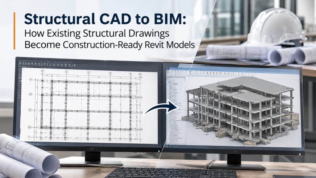
With increasing complexity of building projects, more and more architectural and engineering companies use Building Information Modeling (BIM) in order to create an integrated and coordinated structural model. Conversion of the existing structural drawings into Autodesk Revit model allows transforming an isolated set of 2D drawings into an information-rich model of a building structure.
The conversion of structural CAD drawings into BIM models in Revit is a complex task that includes much more than simply importing DWG files into Revit and tracing existing geometry.
This process involves interpretation of engineering documentation, establishment of structural connections, levels, and grids, and development of model elements with the proper dimensions and parameters.
This article describes the process of converting existing structural CAD drawings into Revit models, required information before starting to model, potential difficulties in this process, and necessary model quality checks.
Why Structural CAD Drawings Need More Than 2D Documentation?
The conventional structural drawing in CAD uses plans, elevations, sections, schedules, and construction details to convey engineering information. While all these drawings are essential during the design and construction process, they only depict the components of the structure in two dimensions.
It becomes challenging to understand how the structural components integrate with other systems when multiple disciplines are involved in the project.
For instance, the structural framing plan may show where the beams are positioned and their size, while the architectural drawing depicts where there are openings on the floor and the MEP drawings show the positions of pipes and ducts.
Structural BIM Model eliminates these drawbacks by providing building components in the form of coordinated 3D elements.
Among the shortcomings of conventional structural CAD documentation are the following ones:
Insufficient spatial perception: Engineers and contractors have to analyze a number of plans and sections in order to understand the overall structure arrangement.
Uncoordinated drawing data: Foundational plans, framing plans, elevations and structural details may have similar data which is not interconnected.
Need for manual coordination: It is necessary to compare structural drawings with architectural and MEP documents.
Problems with design modification: Any changes in structural dimension and positioning of structural components may involve revision of all drawing sheets.
Lack of integrated information: Common 2D CAD geometry lacks component information which is characteristic of a BIM model.
Transformation of structural CAD drawings into Revit leads to more coordinated environment of the project. Structural components such as foundations, columns, beams, slabs, walls etc. can be converted into separate model components having specific properties.
The process helps engineering companies to achieve better visualization, design coordination, quantization, documentation and communications.
What Information Is Required Before Structural BIM Modeling?
Accuracy of the structural BIM model highly depends on the accuracy of the original documents.
It is important to conduct an analysis of all structural drawings and define the data needed for creating the Revit model.
Insufficient information or discrepancies in the drawings can lead to modeling assumptions that will impact the process of coordination.
The list of necessary information is as follows.
Structural CAD Drawings
Main input consists of the existing structural drawing set, preferably in DWG format.
Depending on the size of the project, it can include:
- Plans of foundations and footings
- Column layout plans and schedules
- Plans of beams and girders framing
- Structural slab layouts
- Details of structural walls and shear walls
- Plans of roof framing
- Sections and elevations of structures
Details of reinforcement and connections, when included in the agreed scope of work.
Architectural Reference Drawings
The architectural reference information is crucial for structural modeling, especially in the coordination of floor elevations, layout of buildings, openings, and spatial relationships.
The reference information includes floor plan, building section, level of the finished floors, wall layouts, staircases, elevator shafts, and architectural openings.
The architectural references aid in identifying differences between architectural and structural layouts before the coordination problem arises.
Structural Specifications and Schedules
The structural specifications and the schedule give some information which might not be reflected in the plan geometry.
Some of these are:
- Concrete strength and material specification
- Steel grade
- Column and Beam sections
- Thickness of the slab
- Foundation dimensions
- Designation of the structural members
Reinforcement specifications, if modeling is needed.
Project Coordinates and Level Information
It is also important for the modeling team to define the coordinate system and elevation datum for the project.
The following are some of the inputs that are required:
- Building grid references
- Base point information
- Survey point information
- Heights of floors above other floors
- Elevations of foundations
- Elevations of finished floors
- Common coordinates, if any
- Units of the project and standards of measurement
Pre-modeling analysis is critical: In case drawings have inconsistent dimensions, missing elevations, or ambiguities in the designation of members, it must be brought to the attention of the design team.
Converting Structural CAD Drawings into Revit Elements
CAD-to-BIM structural modeling requires interpretation of drawing data and re-drawing the same using proper structural elements in Autodesk Revit.
The aim here is to create a model representing the structure of the building and not just creating an image similar to the existing DWG drawings.
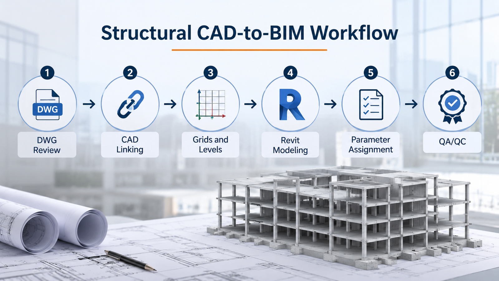
Some of the steps involved in the process of conversion are as follows.
Step 1: Review and Prepare the CAD Drawings
Prior to the importation of the drawings in Revit, the modeling team reviews the DWG drawings for any unwanted layers, duplicates, units, linework, references, etc.
Common activities performed are:
- Deleting redundant layers in CAD drawings.
- Checking units of drawings and measurement scale.
- Checking Xrefs.
- Checking for missing annotations.
- Orientation and coordinates of the drawing.
- Structural elements vs. Drafting elements separation.
Step 2: Import or Link CAD References into Revit
The next step is to link or import the drawings to the relevant Revit views.
CAD files are better to be linked in terms of future coordination because this way, they will have a reference connection with their source drawings.
The modeling group needs to check the import parameters, such as units, positioning, and orientation, in order for the CAD reference to be placed properly in the project environment.
Step 3: Creation of Structural Grids and Levels
Structural grids and levels are a referencing system used for the placement and arrangement of the building components.
The team makes necessary grid lines and elevation levels according to the approved structural plans.
This way, they will maintain consistent positioning of the foundations, columns, beams, slabs, and other elements.
Step 4: Replicating Structural Elements
The next step in the process will involve modeling of Revit elements of the structure.
Depending on the scope of the project, the following could be among those that will need to be created:
- Structural foundations
- Isolated and continuous foundations
- Structural columns
- Beams and girders
- Structural framing systems
- Concrete slabs
- Structural walls
- Structural bracing and other structural elements
All structural elements will need to be created with respect to the appropriate Revit category and family with respect to their dimensions and properties.
Step 5: Assignment of Parameters and Structural Properties
After creation of the geometry, parameters and properties of the elements will be assigned to the model elements.
These may include but are not limited to materials, member sizes, classifications, reference levels, offsets, and other project-specific parameters.
Modeling Foundations, Columns, Beams and Slabs
Accurate representation of the building load-bearing system and interaction between it and other building elements is the primary aim of BIM structural modeling.
Each building element needs specific approaches in terms of its geometry, documentation and desired modeling level.
Foundation Modeling
Foundation elements transmit building loads to the soil underneath and other foundation systems.
Types of foundation elements may include:
- Individual spread footings
- Combined footings
- Strip and continuous foundations
- Raft foundations
- Pile caps
- Grade beams
- Foundation walls
These types of elements could be modeled using corresponding foundation structural families in Revit.
The model needs to represent dimensioning, location and interrelationship of foundation elements.
For instance, the individual footing should be positioned correctly under its corresponding column, grade beams need to be aligned with approved foundation plan.
Structural Column Modeling
Columns refer to vertical load bearing elements that transmit loads from one structural level to another.
In general, structural columns in the Revit model are defined using structural column families of Revit with the dimensions and locations derived from column schedules and framing plans.
Critical aspects of the column modeling process include the following:
- Column section dimensions
- Column center line alignment
- Base and top restraints
- Vertical offsets
- Materials
- Column continuation through floors
- Changing sizes of columns at different floors
Locations of columns should be consistent with the locations defined by the structural grid system.
Beam and Girder Modeling
Beams and girders are load bearing elements that carry loads from floor systems to columns, walls, and other structural supports.
Structural framing elements are modeled using appropriate Revit beam family and profiles.
The modeling team needs to check the following parameters in the modeling process:
- Width and depth of beams
- Locations of start and end points
- Elevations and vertical offsets
- Orientation of beams
- Relationships and connections
- Framing alignment with columns and walls
Structural Slab Modeling
Structural slabs serve as horizontal structures transferring loads from floors and roofs onto the structural system.
Depending on the project, it might be necessary to model slabs as Revit floors designed for structural use.
Some of the crucial factors are:
- Slab thickness
- Boundary shape
- Upper and lower elevations
- Slab holes
- Edges
- Material characteristics
- Relationships between structural components
It is necessary to model the holes in slabs for stairs, elevators, shafts, and MEP penetrations according to the approved drawings.
The main idea of modeling structural BIM models: each structural element should be designed with appropriate geometry, location, and characteristics. An analogous visual model is not always an accurate structural BIM model.
Managing Structural Levels, Grids and Coordinates
The structural level, the grid, and the coordinates form the spatial reference for a Revit model. In case these references are incorrect, the accurate foundation, column, beam, and slab models could be out of place.
It is therefore one of the most crucial steps in the process of CAD-to-BIM conversion.
Creation of Structural Grids
Structural grids provide the horizontal reference for the location of building elements.
They are usually determined by numbered and lettered grid lines in the structural drawings.
During conversion, the following must be done by the modeling team:
- Recreation of the grid system in the drawings.
- Observance of proper distances between grid lines.
- Intersection of grids with structural column locations.
- Comparison with architectural reference grids.
- Consistency in grid naming.
- Creation of grids helps in determining the right location of structural members.
Creating and Managing Structural Levels
Levels refer to key elevations in a horizontal plane of the building structure.
Examples of structural levels include:
- Foundation Level
- Basement Level
- Ground Floor Level
- Floor Levels
- Roof Level
- Mechanical/equipment Level
Every level must match the elevation indicated in the structural drawings.
While creating columns and beams, proper base and top constraints must be applied to keep them vertically aligned.
It is equally important to compare the floor elevations in the structural drawing with those in the architectural drawings. This comparison is necessary since there might be some differences between the two.
Managing Project Coordinates
Coordinated management will be of utmost importance while dealing with large-scale structures, construction phases, renovations, and models involving more than one consultant.
Within Revit, one will be able to use project base points, survey points, and shared coordinates to aid in coordinating the placement of models.
Modeling team should verify the following:
- Project origin and coordinate references.
- Points of drawings insertion.
- True North and project North orientation.
- Elevations references.
- Coordination with architectural and MEP models.
- Need for shared coordinates.
Incorrect coordinate management can lead to displacements of linked models and alignment issues.
The biggest distinction is that drawings are used to convey the design in CAD, while geometry and other project information are connected in BIM, making it easier to manage throughout the development.
How Structural BIM Models Support Architectural and MEP Coordination?
One of the benefits of using structural CAD drawings for Revit modeling is the coordination of the structure with other models such as architecture and MEP.
Traditionally, engineers used different packages of drawings to detect conflicts; however, in a BIM environment, all parties will be able to see all building systems together and find possible clashes.
Architectural Coordination
The models of structures and architecture must co-exist to ensure that the design of the building is maintained.
Some of the common areas of coordination are:
- Columns of the structure and walls of the architecture.
- Depth of beams and ceilings.
- Edges of the slab and façades.
- Openings for staircase and lifts.
- Elevation of floors and architectural finishes.
- Walls of the structure and door/window openings.
For instance, a column of the structure could encroach on the corridor of the architecture or affect the positioning of the walls.
MEP Coordination
MEP systems require adequate room in ceilings, floors, shafts, and service corridors.
The structural system can lead to limitations in routing of ducts, pipes, cable trays, and other building systems.
Examples of typical coordination issues are:
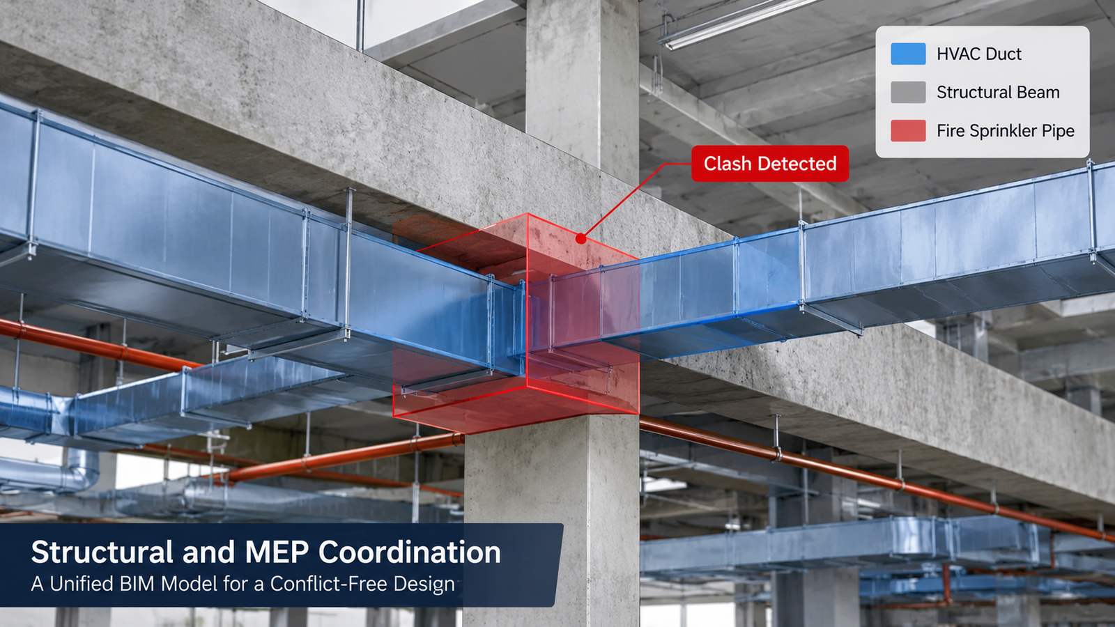
- HVAC ducts going through beam areas.
- Plumbing pipes penetrating through structural slabs.
- Cable trays conflicting with the structural frame.
- MEP penetrations through structural walls.
- Equipment clearances around columns and beams.
- Service penetrations through structural shafts.
A coordinated structural BIM model will give you the geometry required to detect these potential conflicts.
Clash Detection and Model Review
In the case when all three types of models are integrated together, then it becomes possible for the project teams to do model-based coordination checks.
Such applications as Autodesk Navisworks and others can be used to find hard clashes and do a check on spatial conflicts.
For example, a big HVAC duct can clash with a structural beam. The coordination team will be able to identify the conflict, mark its location and inform the responsible design discipline.
It is necessary to understand that the process of clash detection is one thing while the approval of design change is another.
Any modification to the structural elements, structural penetrations and load-bearing items should be checked and approved by the responsible structural engineer.
Common Challenges When Converting Existing Structural Drawings
Conversion difficulties that may arise when trying to transform existing structural drawings into Revit models are varied and numerous.
These problems become especially evident when dealing with renovation projects and older buildings, as well as cases when the CAD documentation is not complete.
This knowledge assists in building an effective model conversion process.
Incomplete or Outdated CAD Drawings
In some projects, there will be structural drawings which do not represent the present state of the structure or latest design modifications.
Recommended approach: the foundation drawing can have an old footing layout, and the revised drawing will have the new sizes. Advice on handling the problem:
Check drawing modifications, identify the latest approved drawings, and look out for any differences prior to modeling. For existing structures, determine if you need any field verification or laser scanning.
Missing Dimensions and Structural Details
All structural CAD drawings do not have full dimensioning, elevations, and/or section sizes.
Sometimes a beam may be shown on the framing plan with inadequate information regarding its actual section size and elevations.
Recommended approach: Compare the structural sections and schedules for any missing information and get it clarified rather than estimating the important dimensions.
Inconsistent Drawing Scales and Units
However, there can be discrepancies in the units of measurement, coordinate system, or the scale of the drawing amongst other CAD files by different consultants.
The issues can make it difficult to align different drawings imported in Revit.
Recommended approach: Ensure all these are correctly aligned before importing the drawings. Compare the measurements with original drawings.
Complex Structural Geometry
The structural systems that include transfer beams, sloped members, grid modification, curved elements, and varied slab levels require additional explanation.
It may be difficult for standard methods of modeling structures to represent all structural systems.
Recommended approach: Use the right Revit family elements and structural framing as required. Check the complex geometry using approved sections and details.
Differences Between Structural and Architectural Drawings
The building plan and the structure plan may have differing positions for walls, openings, floors, or columns.
This could result in inaccuracy and lack of correlation in the model.
Recommended approach: Keep separate discipline references, note any discrepancies, and coordinate with the relevant design team before making changes.
Modeling at the Wrong Level of Development
Creating too much or too little level of detail relative to the project requirements is another frequent problem.
A model that is designed to coordinate early during the design phase would need different information than the one designed to document for construction or fabrication.
Recommended approach: Define the LOD, scope of modeling, element types, and deliverables to be delivered before initiating the conversion process.
Quality Checks for Accurate Structural BIM Models
The importance of quality control is vital in order to ensure that a structural Revit model will effectively represent all of the data found in the original CAD drawings.
The model might appear accurate and complete through 3D visualization but still have incorrect dimensions, misplaced elements, missing components, or inconsistent properties.
The use of a structured process of quality control will help detect such problems at an earlier stage.
Geometric Accuracy Checks
The first step involves verification of the geometry of the model from the structural drawings.
The important aspects that have to be checked are:
- Dimensions of the foundation and location.
- Dimensions of the columns and their centerlines.
- Beam sizes and their framing.
- Thickness of the slab and their boundary conditions.
- Location of the structural walls.
- Opening and cutouts.
- Vertical and horizontal offsets.
Level and Grid Verification
All the elements must be located properly according to structural grids and levels.
The quality assurance process must include:
- Grid distances and nomenclature.
- Level elevations.
- Column bottom and top restrictions.
- Beam elevations.
- Foundation locations.
- Alignments with architectural references.
This would help to avoid any systematic problems in locating elements throughout the building.
Structural Element and Parameter Checks
It is necessary to validate each element and check whether it belongs to the correct category in Revit and whether it contains all the necessary information.
Here are some examples:
- Columns should belong to the category of structural columns.
- Beams should belong to the category of structural framing.
- Foundation elements should belong to the category of foundations.
- Structural slab configuration should be provided.
- All material and member size information should meet project requirements.
Multidisciplinary Coordination Checks
Verification of the structural model is required in relation to architectural and MEP information that is available.
It is important for the group to consider potential conflicts that might arise based on:
- Framing system and HVAC systems.
- Column layouts and architectural designs.
- Opening in slab and MEP penetrations.
- Structural walls and service routes.
- Ceiling height and beam depth.
Model Integrity and Deliverable Review
Before sending the Revit model, it needs to undergo a technical check of its final form.
The list might consist of:
- Detecting possible duplicates in the model.
- Inconsistencies and warnings check.
- Checking the links between the CAD and Revit files.
- Workset and views check (when required).
- Checking the naming convention.
- Units and coordinates check in the model.
- Checking all deliverables that were supposed to be delivered.
The last comparison of the Revit model with the original documentation will make it easier to identify whether the scope was completed successfully.
In addition, it is important to record assumptions of the model, which were not resolved.
When Should Engineering Firms Outsource Structural CAD to BIM?
Conversion of Structural CAD to BIM model necessitates the expertise of structural drawings, Revit modeling, and multi-disciplinary coordination process.
Though some engineering companies have a BIM team within them, outsourcing could become a suitable alternative in case the requirements of the projects exceed their capacity.
The following instances could warrant an engineering company to outsource the services of converting structural CAD to BIM.
High Number of Structural Drawings
Projects that involve several buildings, several floors, or high structural drawings would necessitate a lot of modeling efforts.
A BIM team from outside would assist in converting those drawings into Revit models, and at the same time, the internal engineers would concentrate on technical issues.
Tight Project Delivery Schedules
As the time of project completion draws near, the internal team may discover that they have difficulties maintaining the balance between design and CAD to BIM translation.
Outsourcing will provide additional resources and better organization of the modeling process.
Lack of Revit Expertise Internally
Cases where the structural engineer was well acquainted with structure design but lacked proper allocation of BIM modeling were known.
Through the support of structural BIM modeling services firm, such a drawback can be overcome without the need for purchasing more software, employing extra staff, or investing in personnel.
Renovation and Existing Buildings Projects
Rehabilitation usually consists of old drawings, insufficient documentation, and complex existing conditions.
A professional modeling company can understand the information and model in Revit for the rehabilitation projects.
Final Words
The conversion from structural CAD drawings to construction-ready Revit models is a systematic process, which goes beyond duplicating the existing 2D drawings. The process consists of interpreting structural drawings, defining the correct grids and levels, creating Revit elements with correct category, attributing properties to them, and checking the model for compliance with the engineering drawings.
Once done right, structural CAD-to-BIM conversion will result in the creation of a more organized digital model of the building structure. It will become possible for architects, engineers, and contractors to use the created model for multidisciplinary coordination, clash detection, design review, and other purposes.
In cases when the company is responsible for large packages of drawings, renovation works, or tight deadlines, collaboration with a BIM modeling partner may be helpful.
NDA available

