

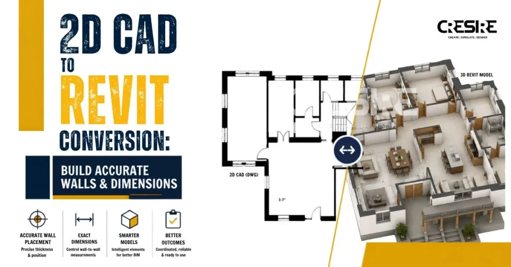
Many architectural and engineering projects still start with 2D CAD drawings. The DWG file might have lots of valuable data from previous years relating to the project – floor plans, elevations, sections, dimensions, grids.
The problem arises when this data must be brought to a BIM process.
A DWG can be linked into Revit and used as an underlay for modeling, but that does not make it a BIM model. The real CAD to Revit conversion process involves interpreting the drawing and rebuilding its relevant information as native Revit elements.
Walls are a good example. A CAD drawing may show two lines representing a 150 mm partition, but the Revit model needs to know the wall type, thickness, location, constraints and relationship to surrounding elements.
This is where accurate modeling decisions become important.
What Does 2D CAD to Revit Conversion Involve?
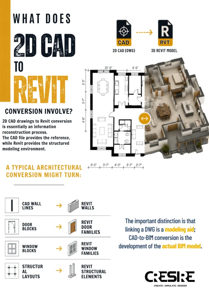
2D CAD drawings to Revit conversion is essentially an information reconstruction process. The CAD file provides the reference, while Revit provides the structured modeling environment.
A typical architectural conversion might turn:
- CAD wall lines → Revit walls
- Door blocks → Revit door families
- Window blocks → Revit window families
- Structural layouts → Revit structural elements
Autodesk itself demonstrates using linked CAD data as an underlay for placing walls, doors and windows in Revit.
The important distinction is that linking a DWG is a modeling aid; CAD-to-BIM conversion is the development of the actual BIM model.
How to Convert 2D CAD Drawings to Revit
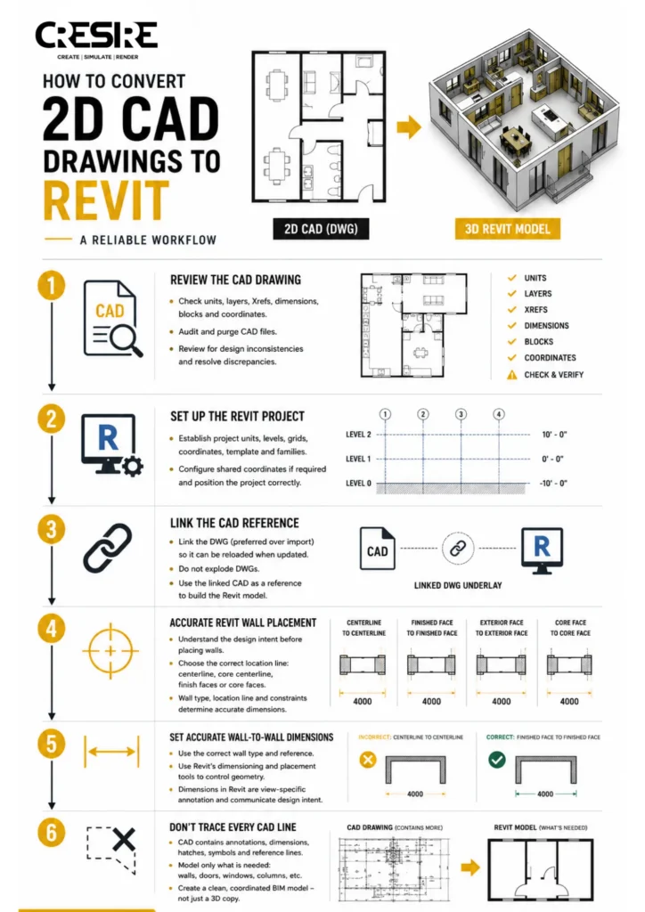
A reliable workflow starts before the first wall is modeled.
1. Review the CAD Drawing
First, check the drawing’s units, layers, Xrefs, dimensions, blocks, coordinates and overall drawing health.
This matters particularly with legacy CAD files. Unnecessary hatch patterns, site information or other unused data can make large DWGs more difficult to manage. Autodesk recommends auditing and purging CAD files and removing unnecessary data before linking them into Revit.
More importantly, review the drawing for design inconsistencies.
If two dimensions conflict with the apparent geometry, don’t simply choose whichever value makes modeling easier. Identify the discrepancy before it becomes part of the BIM model.
2. Set Up the Revit Project
Establish the project units, levels, grids, coordinates, template and required families before detailed modeling starts.
For projects using shared coordinates, the CAD reference should also be positioned correctly within the project environment. Autodesk supports linking site DWGs using shared coordinates when the appropriate project/survey coordinates are available.
3. Link the CAD Reference
For an active CAD-to-Revit workflow, linking the DWG is often preferable to importing it because a linked file can be reloaded when the source drawing changes. Autodesk also recommends avoiding unnecessary DWG explosions in Revit.
The CAD file then becomes the reference against which the native Revit model is developed.
The Most Important Part: Accurate Revit Wall Placement
Once the CAD reference is in place, wall modeling appears straightforward—but this is where many conversion errors begin.
Suppose a CAD floor plan shows a room dimension of 4,000 mm.
The critical question is: 4,000 mm between what?
It could be:
- Wall centerline to centerline
- Interior finished face to interior finished face
- Exterior face to exterior face
- Core face to core face
These are not interchangeable.
Revit provides different wall location references, including wall centerline, core centerline and finish/core faces. The wall’s construction layers and core boundaries also affect how those references behave.
Why the Location Line Matters
Consider a 150 mm internal partition.
If the architectural design controls the clear internal room dimension, placing the wall from its centerline may not be the most appropriate modeling approach.
If the design controls the structural core, however, the core face or centerline may be more relevant.
The correct choice depends on the design intent, not simply on which CAD line is easiest to trace.
How to Set Accurate Wall-to-Wall Dimensions in Revit
This is particularly important when converting dimensioned architectural floor plans.
Imagine the CAD drawing specifies:
Room width = 4,000 mm, measured from the inside face of one finished wall to the inside face of the opposite wall.
If the Revit walls are positioned using their centerlines, the modeled room may not produce the intended internal dimension. The solution isn’t necessarily to manually calculate wall thickness every time.
Instead, establish the correct wall type and reference, then use Revit’s dimensioning and placement tools to control the geometry.
Revit dimensions are view-specific annotation elements and can be used to communicate building widths, lengths and feature locations.
The key distinction is: The dimension should reflect what the design is controlling.
For room planning, that may be the finished interior face. For structural coordination, it may be the structural core. For another condition, the centerline may be appropriate.
Don't Trace Every CAD Line
A common mistake in CAD to Revit wall modeling is treating every line in the DWG as something that must become a Revit element.
It doesn’t.
CAD drawings contain information intended for graphical documentation—dimensions, hatches, annotation, reference lines and symbols.
The BIM model should contain the building information required for its intended use.
For example, a wall should become a wall; a door should become a door family; and a structural column should become an appropriate structural element.
This produces a cleaner and more useful model than simply reproducing the appearance of the CAD drawing in three dimensions.
What Should Be Checked After CAD to Revit Conversion?
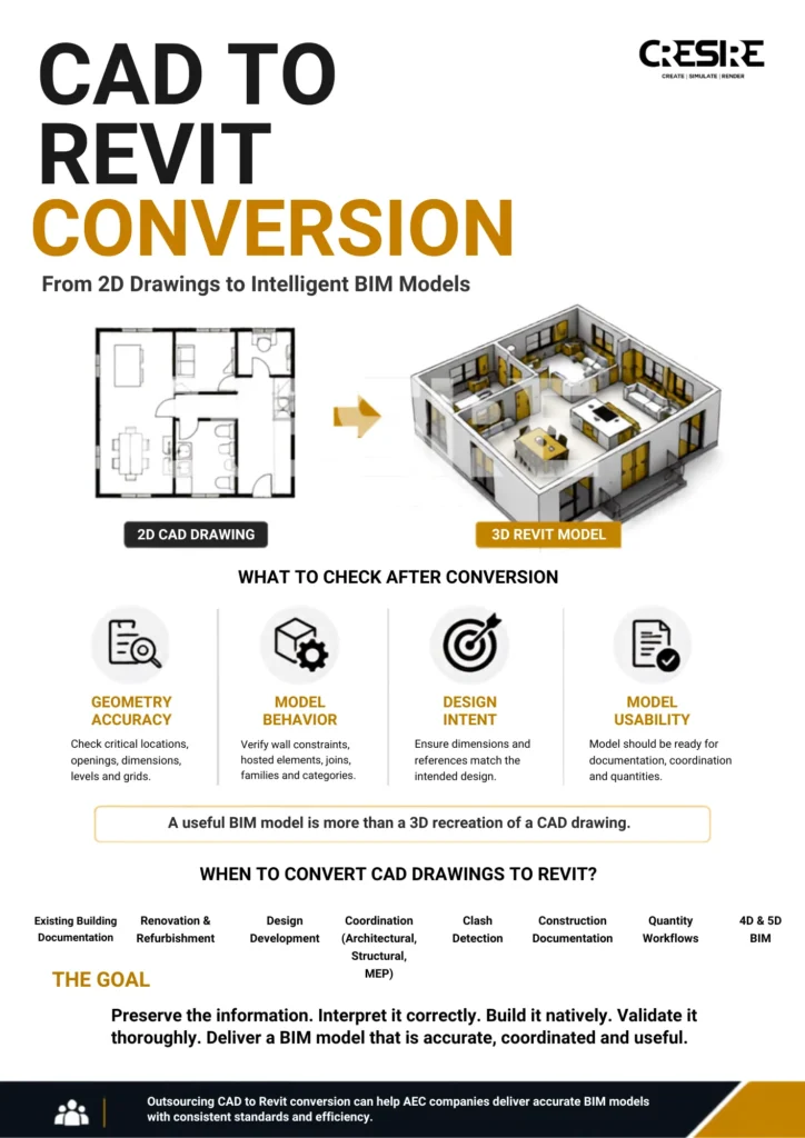
Visual similarity alone isn’t enough. A good review should ask:
Does the geometry match?
Check critical wall locations, openings, dimensions, levels and grids against the source drawing.
Does the model behave correctly?
Check wall constraints, hosted elements, joins, families and categories.
Does it preserve design intent?
A room dimension that was intended to be controlled from finished faces should not accidentally become a centerline-controlled dimension.
Is the 3D Revit model usable downstream?
The model should be structured appropriately for documentation, coordination, quantities or other agreed uses. This is what separates a 3D recreation of a CAD drawing from a useful BIM model.
When Should CAD Drawings Be Converted to 3D Revit?
CAD-to-BIM conversion becomes particularly valuable when existing drawings need to support more than basic 2D documentation. Common use cases include:
- Existing building documentation
- Renovation and refurbishment
- Design development
- Architectural coordination
- Structural coordination
- MEP coordination
- Clash detection
- Construction documentation
- Quantity workflows
- 4D and 5D BIM
For a small drawing that will never be developed further, CAD may be sufficient. But when the project needs coordinated, editable and reusable building information, developing a BIM model can provide considerably more value.
CAD to Revit: The Goal Is More Than a 3D Model
A successful 2D CAD drawings to Revit workflow should preserve the important information contained in the original documentation while giving the project team a more structured environment to work in.
That means: CAD reference → correct interpretation → native Revit elements → accurate dimensions → validated BIM model
For walls in particular, small decisions about wall type, location line and dimension references can have consequences across the rest of the project.
The objective should therefore not be to create a model that merely looks like the CAD drawing.
It should be to create a model that represents the documented design accurately and behaves as a useful BIM model.
For AEC companies with large CAD drawing sets or limited internal Revit capacity, outsourcing the conversion can also provide a practical way to develop these models while maintaining project-specific LOD, templates and modeling standards.
NDA available