

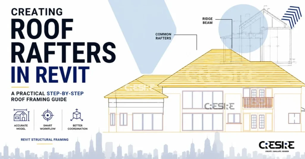
Creating roof rafters in Revit can look straightforward until the roof becomes more than a simple rectangle.
The roof may have multiple slopes, different framing directions, valleys, hips, openings, overhangs or changes in elevation. At that point, simply placing beams along a roof plane isn’t enough. The framing needs to follow the geometry of the roof and remain consistent with the structural design.
This is where roof rafters in Revit modeling become particularly useful.
Revit provides several ways to develop roof framing, including individual structural framing elements and beam systems. The right approach depends on the roof geometry, framing pattern, level of detail and what the model needs to support later.
For a straightforward repetitive roof, a beam system can create a series of parallel framing members efficiently. For irregular roofs or situations where individual rafters need specific positioning, structural framing elements may provide more control. Autodesk’s Revit documentation also notes that beam systems can be used to place a series of individual beams in parallel, and that non-planar beam systems can be used where framing follows varying elevations.
The important part is not simply getting rafters to appear in 3D.
The goal is to develop a roof structure that accurately reflects the intended framing arrangement and can be coordinated with the rest of the building.
What Are Roof Rafters in Revit?
In a Revit structural model, roof rafters are generally represented using structural framing elements arranged to support the roof assembly.
Depending on the project, rafters may be timber, steel or another structural framing type. Their section, spacing, orientation, slope and relationship with supporting elements are determined by the structural design.
A typical roof framing model may include:
- roof rafters;
- ridge beams;
- hip and valley framing;
- purlins;
- joists;
- roof trusses;
- structural beams;
- posts and supports;
- bracing;
- roof openings and framing around them.
Not every roof requires all of these elements.
A simple pitched roof may only need repetitive rafters between supporting walls or beams. A more complex roof may require several framing systems working together.
This is why Revit rafter modeling should start with an understanding of the structural concept rather than simply the roof’s visual geometry.
Before Creating Rafters: Understand the Roof Geometry
One of the most common mistakes is to begin placing rafters before checking how the roof itself has been constructed.
A roof may have a defined slope, overhang, ridge location and supporting perimeter. The rafters need to relate correctly to those conditions.
Before revit modeling, review:
- roof slope;
- roof planes;
- ridge locations;
- eaves;
- overhangs;
- supporting walls and beams;
- valleys and hips;
- roof openings;
- changes in elevation;
- framing direction.
Sections are particularly useful here.
A plan may show the footprint of the roof, but a section reveals the vertical relationship between the roof, supporting structure and framing.
If the roof geometry is wrong, accurate-looking rafters can still produce an incorrect Revit roof structure.

Step 1: Set Up Levels and Structural References
Start with the structural framework that the rafters will reference.
Levels should correspond to the project’s established building elevations. Structural grids and supporting elements should also be checked where they are relevant to the roof framing.
This is especially important on projects where the architectural and structural models are linked.
A roof may appear to sit correctly against the architectural model while the structural framing is based on slightly different elevations or coordinates.
Before creating rafters, verify that the model is working from the correct project references.
That small amount of preparation can prevent a lot of adjustment later.
Step 2: Select the Appropriate Structural Framing Family
Rafters are generally modeled using an appropriate structural framing family rather than a generic architectural component.
The selected family should represent the required structural member and contain the information needed for the project.
For example, the framing type might represent a timber rafter, steel section or another structural member depending on the design.
The choice matters because the family controls more than appearance.
Section geometry, structural properties, identity information and other parameters can affect how the element behaves and is documented within the model. Revit’s structural framing tools support different framing element behaviors and properties for structural modeling.
If the required rafter section is not available in the project, an appropriate family may need to be loaded or developed before continuing.
Step 3: Decide Between Individual Rafters and a Beam System
This is one of the most important decisions in the workflow.
Use individual structural framing when:
- the roof geometry is irregular;
- rafter locations vary;
- individual members need different lengths;
- hips and valleys require specific framing;
- openings interrupt the regular pattern;
- each member needs individual control.
Consider a beam system when:
- rafters repeat at regular spacing;
- the framing follows a consistent direction;
- the supporting boundary is clearly defined;
- many similar members need to be created efficiently.
A beam system provides a way to create a series of parallel structural framing elements within a defined area. Revit allows the layout rule, spacing, beam type and beam direction to be controlled through beam system properties.
For a regular pitched roof, this can save considerable modeling time.
For a complex roof, however, forcing everything into one beam system can create more problems than it solves.
Step 4: Create the First Rafter
If individual framing members are being used, place the first rafter between its intended support points.
The rafter needs to follow the roof slope rather than simply sitting horizontally beneath the roof.
In an elevation or 3D view, check:
- start and end elevations;
- rafter slope;
- member orientation;
- support conditions;
- overhang;
- relationship with the roof surface.
This first member becomes a useful reference for the rest of the framing.
Don’t immediately copy hundreds of rafters.
First make sure one rafter is correct.
Step 5: Set the Rafter Slope and Orientation
The rafter should follow the intended roof pitch.
This is where a section view can be more useful than a plan view.
A rafter that looks correctly positioned in plan may still have the wrong elevation or orientation.
Use the available Revit controls and reference geometry to confirm that the framing follows the roof slope and meets the supporting structure correctly.
For sloping or non-planar framing arrangements, Revit’s beam system tools provide options for defining non-planar systems and controlling the framing direction.
The exact method depends on how the roof and structural system have been modeled.
Step 6: Set Rafter Spacing
Once the first member is established, the next question is repetition.
Rafter spacing should follow the structural design rather than being chosen simply because it looks evenly distributed.
For repetitive framing, a beam system can be particularly useful because Revit allows the layout rule and spacing requirements to be defined for the system.
Depending on the project, the framing may be controlled by:
- fixed spacing;
- number of members;
- maximum spacing;
- minimum spacing;
- alignment or justification.
The correct setting depends on the design requirements and the project’s modeling standards.
A Small Detail That Matters: Justification
Even when the spacing is correct, the framing can appear incorrectly positioned if the system justification is not set appropriately.
For example, the design may require the first rafter to align with a specific edge or reference condition rather than simply distributing members symmetrically.
Check the beginning and end of the framing pattern.
Small differences at the roof edges can become noticeable when the model is used for construction documentation.
Step 7: Extend the Rafters to the Eaves
Rafter modeling doesn’t end when the member reaches the roof boundary.
The eaves and overhang need to reflect the structural design.
Depending on the roof assembly, the rafters may extend beyond the supporting wall or terminate at a specific structural line.
Check the relationship between:
Roof edge → fascia/eaves → supporting wall → rafter end
The correct rafter extension should come from the project design rather than simply matching the visible roof overhang.
This is one reason it is useful to compare the model against sections and structural details rather than relying only on the architectural roof plan.
Step 8: Model Ridge, Hip and Valley Framing
Simple roofs are relatively easy.
The complexity increases when roof planes meet.
At ridges, hips and valleys, the regular rafter pattern may no longer be sufficient. Additional structural members may be required to support the roof geometry.
These members should be modeled according to the structural design.
A hip or valley member may need a different orientation or section from the regular rafters. The surrounding rafters may also require different lengths or termination conditions.
This is an area where individual structural framing elements can provide more control than trying to force an irregular arrangement into a standard beam system.
Step 9: Add Roof Openings and Framing Around Them
Roof openings create another break in the regular framing pattern.
Skylights, roof access, mechanical equipment, ducts and other penetrations may require framing changes.
The opening should be considered together with the structural framing rather than being treated as a purely architectural feature.
For example, if a mechanical unit requires a roof penetration, the structural team may need additional framing around the opening.
Modeling that relationship in Revit makes the interface easier to review with the architectural and MEP teams.
Step 10: Check Rafter Connections and Intersections
Once the roof framing has been developed, inspect how the members meet.
Look for:
- rafters terminating correctly at supports;
- ridge connections;
- hip and valley intersections;
- framing around openings;
- beam-to-rafter relationships;
- posts and supporting elements;
- unintended overlaps.
Revit’s structural framing environment provides tools for controlling framing element geometry and relationships, including joins and cutbacks.
However, a visually clean connection does not automatically represent an engineered connection.
The BIM model should reflect the structural design intent and the agreed level of development.
Step 11: Review the Roof Framing in 3D and Section
Never rely on a single plan view to verify roof rafters.
Use a combination of:
Plan views to check spacing and framing direction.
Sections to check slope, elevation and support relationships.
3D views to review the overall roof structure and intersections.
This is particularly important for multi-slope roofs.
A framing arrangement that looks correct from above can reveal a completely different problem in section.
Three-dimensional review is one of the practical reasons Revit structural framing is useful: the project team can inspect the framing from several perspectives without recreating separate drawings for every viewpoint.
When Should You Use a Beam System for Roof Rafters?
Beam systems are especially useful when a roof contains a repeated series of similar framing members.
For example, consider a simple timber pitched roof where rafters are spaced consistently between two supporting boundaries.
Creating every rafter individually would work, but it is unnecessarily repetitive.
A beam system can create the repeated framing pattern more efficiently and allow the team to control beam type, spacing, layout rule and direction. Autodesk specifically documents beam systems as a method for placing a series of parallel structural framing elements and notes their use for wood roof rafters.
However, there are situations where individual rafters are preferable.
Complex roofs, varying spacing, multiple framing directions, openings and irregular support conditions can all make individual modeling more practical.
The best workflow is the one that matches the geometry.
Common Problems When Modeling Roof Rafters in Revit
Even experienced Revit users can run into problems with roof framing.

Rafters Are Horizontal Instead of Following the Roof
This usually points to an issue with the placement plane, elevation, slope or framing setup.
Check the rafter in section rather than trying to correct the problem from plan view alone.
Rafters Do Not Meet the Roof Correctly
The roof geometry and structural framing may not be referencing the same elevations or intended support conditions.
Review the roof section and the rafter’s start and end conditions.
Rafter Spacing Is Incorrect
Check the beam system layout rule, spacing, justification and boundary conditions.
Also confirm whether the design calls for a specific spacing rather than a generic evenly distributed arrangement.
Rafters Extend Too Far
Check the intended eave or overhang condition against the structural details.
Don’t assume that the visible roof edge represents the structural rafter termination.
Beam System Does Not Work With the Roof Shape
A single beam system may not be appropriate for a complex or multi-plane roof.
Divide the framing into logical systems or use individual structural framing members where greater control is required.
Roof Framing Looks Correct but Does Not Coordinate
This is often a multidisciplinary issue rather than a framing issue.
Check the rafters against architectural roof geometry, structural supports, MEP penetrations, equipment and other building elements.
Roof Rafters Are Part of a Larger Structural Model
It is tempting to treat roof rafters as an isolated modeling task.
In a real project, they rarely are.
Rafters interact with roof assemblies, beams, columns, walls, trusses, openings and other structural elements. They may also need to accommodate architectural features and MEP penetrations.
That is why Revit rafter modeling becomes more valuable when it is part of a coordinated structural BIM workflow.
The model can help project teams understand not only where each rafter sits, but how the roof framing relates to the rest of the building.
What Level of Detail Should Roof Rafters Have?
There is no universal answer.
The required level depends on what the model is being used for.
For an early design model, the primary framing geometry may be enough.
For design coordination, the framing may need accurate sections, slopes, openings and supporting relationships.
For construction-stage work, the model may require substantially more information depending on the project requirements, deliverables and LOD.
The important thing is to define the intended use before modeling begins.
A highly detailed roof model isn’t automatically a better model.
It is better when the added information supports an actual project decision, coordination requirement or deliverable.
How Roof Framing Supports BIM Coordination
A roof rarely belongs to the structural team alone.
Architectural roof geometry, façade interfaces, skylights, mechanical equipment, drainage, penetrations and other services can all affect the framing.
A coordinated Revit roof structure provides a shared reference for reviewing those interfaces.
For example, an MEP contractor may need an opening for a rooftop unit. The structural model can show where the framing sits around that opening. The architect can review the impact on the roof geometry. The contractor can understand the relationship before installation.
That is the broader value of BIM.
The rafter isn’t useful simply because it exists in 3D.
It is useful because other project information can be understood in relation to it.
Final Thoughts
Creating roof rafters in Revit is not simply a matter of drawing beams along a sloped roof.
The roof needs to be understood first: its geometry, slope, supports, framing direction, openings and structural intent. From there, the appropriate Revit workflow can be selected—individual structural framing elements for detailed control, or beam systems where repeated framing makes automation practical.
Once the rafters are modeled, they should be reviewed in plan, section and 3D and checked against the wider architectural and MEP environment.
That is where a roof framing model starts becoming more than a collection of beams.
It becomes useful BIM information.
For structural teams, the goal isn’t to create the most complicated model possible. It is to create a structural model that accurately represents the design, supports coordination and provides the right information for the next stage of the project.
How CRESIRE Supports Revit and Structural BIM Modeling
At CRESIRE, we support architects, structural engineering firms, contractors and other AEC professionals with Revit modeling and Structural BIM Modeling for projects across the USA, UK and other international markets.
Our structural BIM workflows can include roof framing, beams, columns, slabs, foundations, structural walls and other project elements developed from engineering drawings, CAD files, design information and project-specific BIM requirements.
Depending on the project scope, we can also support multidisciplinary coordination by reviewing structural models alongside architectural and MEP information.
The focus is on developing practical, coordinated Revit models that project teams can use for design development, coordination and construction workflows.
Frequently Asked Questions - FAQs
1. Can Revit automatically create roof rafters?
Yes. A beam system can create multiple structural framing members within a defined boundary and apply a selected beam type and spacing rule. This is particularly useful for regular roof framing patterns.
2. What is the difference between a beam and a rafter in Revit?
Both can be represented using structural framing elements, but their role in the structural system differs. A rafter generally follows the slope of a roof and supports the roof assembly, while a beam may perform a broader supporting role depending on the structural design.
3. How do you set rafter spacing in Revit?
When using a beam system, spacing can be controlled through the system’s layout rules and spacing properties. For individually modeled rafters, spacing is controlled by placing or copying members according to the structural design.
4. Can you create sloped rafters in Revit?
Yes. Structural framing elements can be modeled at the required slope, and Revit also supports non-planar beam systems for appropriate framing conditions. The correct method depends on the roof geometry and project requirements.
5. Why are my roof rafters not following the roof slope in Revit?
Check the framing element’s placement, elevation, work/reference plane and slope-related settings. Reviewing the rafter in an elevation or section view is usually more useful than trying to diagnose the issue from a plan alone.
6. Should I use a beam system or individual beams for roof rafters?
Use a beam system when rafters are repetitive and follow a consistent direction and spacing. Individual structural framing elements are generally more flexible for irregular roofs, hips, valleys, openings and variable framing conditions.
7. Can Revit be used for structural roof framing?
Yes. Revit includes structural framing tools for modeling beams and other framing elements, and beam systems can be used to create repeated framing members.
NDA available