


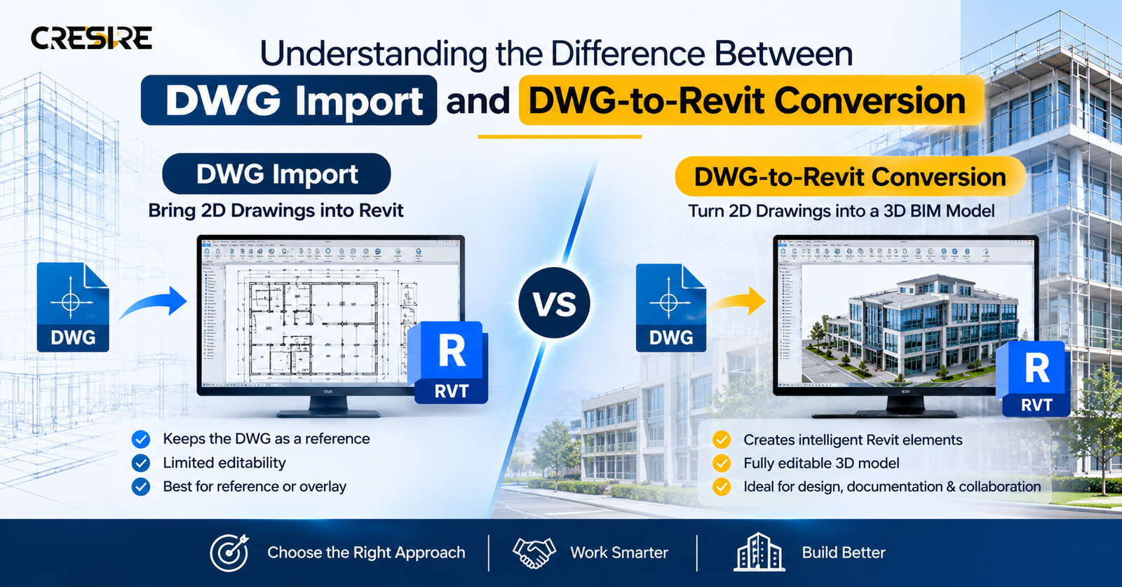
Before starting, it is important to understand that importing a DWG file into Revit does not automatically create a BIM model.
A DWG file generally contains 2D or 3D CAD geometry, such as lines, arcs, polylines, blocks, and annotations. When imported into Revit, this geometry typically remains CAD-based information rather than becoming native Revit building elements.
A proper DWG-to-Revit conversion involves using the imported drawing as a reference and recreating the required building components using Revit tools.
For example:
CAD wall lines become native Revit walls.
Door and window outlines become Revit door and window families.
Column outlines become structural columns.
Stair outlines become modeled Revit stairs.
CAD levels and dimensions are recreated as appropriate Revit datums and annotations.
Structural framing lines become beams and other structural framing elements.
The final model should contain the appropriate native Revit elements, not just an imported DWG file displayed in a 3D environment.
Step-by-Step Workflow to Convert AutoCAD DWG to Revit Model
Step 1: Review and Assess the AutoCAD DWG Files
The first step is to examine the available DWG drawings before importing them into Revit.
A typical project may include architectural floor plans, reflected ceiling plans, elevations, sections, structural layouts, foundation drawings, and MEP layouts.
Start by reviewing the available drawings and identifying which information is required for the Revit model.
Check the following:
Drawing units, such as millimeters, meters, inches, or feet.
Overall building dimensions and floor-to-floor heights.
Wall thicknesses and structural grid locations.
Door and window sizes.
Column, beam, and slab information.
Drawing coordinates and reference points.
Missing dimensions, incomplete geometry, or conflicting information.
Layer organization and unnecessary CAD elements.
Pay particular attention to discrepancies between floor plans, elevations, and sections. For example, a wall position shown in a floor plan may not match the corresponding section.
These issues should be identified before modeling begins rather than carried into the Revit environment.
AEC professional tip: If the project involves existing buildings, confirm whether the DWG drawings represent verified as-built conditions or original design documentation. These are not necessarily the same.
Step 2: Clean and Prepare the DWG File in AutoCAD
A well-organized CAD file makes the conversion process more efficient and reduces unnecessary work during modeling.
Open the DWG file in AutoCAD and remove information that is not required for the Revit model.
Recommended preparation activities include:
Remove unnecessary dimensions, text, hatches, and construction lines.
Delete duplicate or overlapping geometry.
Check and correct disconnected polylines where necessary.
Review layer names and visibility settings.
Remove unused blocks and external references that are not required.
Confirm that the drawing is located near the intended project origin.
Verify that the drawing uses the correct units.
Save a separate, cleaned DWG file for Revit.
Useful AutoCAD commands include:
PURGE – Removes unused blocks, layers, and other definitions.
OVERKILL – Helps remove duplicate or overlapping geometry.
AUDIT – Checks and repairs drawing database errors.
UNITS – Reviews the drawing’s unit settings.
ZOOM EXTENTS – Displays the full drawing extents.
For projects containing multiple CAD references, check whether external references are attached, overlaid, or unresolved. Resolve dependencies before sharing the drawing with the BIM team.
Important: Avoid moving or scaling the original drawing without confirming its coordinate requirements. Incorrect transformations can create alignment problems later, particularly when multiple disciplines are involved.
Step 3: Set Up a New Revit Project
Once the DWG file is ready, open Autodesk Revit and create a new project using an appropriate project template.
The template should reflect the intended modeling discipline, such as architectural, structural, or MEP.
Before importing the CAD drawing, configure the basic project settings.
Set up the following:
Project units.
Levels and floor elevations.
Grids and reference datums.
Project base point.
Survey point, where applicable.
Coordinate system and project location.
Relevant view templates and visibility settings.
For a multi-storey building, establish the required floor levels based on the available elevations and sections.
For example, a building may contain:
Ground Floor: ±0.000
First Floor: +3.600 m
Second Floor: +7.200 m
Roof Level: +10.800 m
These values are illustrative. Actual elevations must be taken from the project documentation.
Setting up levels and grids early provides a consistent reference for modeling walls, columns, beams, slabs, and other building components.
Step 4: Import or Link the DWG File into Revit
After preparing the project environment, bring the AutoCAD drawing into Revit.
Navigate to the appropriate Revit view, usually a floor plan, and use the Insert tab.
There are two commonly used options:
Option A: Link CAD
Link CAD is generally preferred for ongoing projects where the source DWG may be updated by the design team.
Advantages include:
Maintains a connection to the external CAD file.
Allows the linked drawing to be reloaded when revisions are received.
Keeps reference geometry separate from native Revit model elements.
Makes it easier to manage multiple discipline drawings.
Option B: Import CAD
Import CAD brings the DWG geometry directly into the Revit project.
It may be appropriate for static reference information that does not need regular external updates.
However, imported geometry can increase project complexity and make file management more difficult if used excessively.
Recommended import settings:
Colors: Black and White or Preserve, depending on the drawing requirements.
Layers: All or selected layers, depending on the modeling scope.
Import Units: Verify against the original DWG units.
Positioning: Select the appropriate origin or coordinate-based positioning method.
Current View Only: Use when the CAD reference is required only in a specific view.
For most coordinated BIM projects, linking CAD is a practical choice because it provides better control over external drawing revisions.
Step 5: Align the DWG Drawing with Revit Coordinates
Correct positioning is essential for accurate modeling.
If the CAD drawing is imported at the wrong scale or location, the resulting Revit model may not align with other discipline drawings.
Start by checking the relationship between the DWG geometry and the Revit project coordinates.
Common positioning methods include:
Auto – Center to Center.
Auto – Origin to Origin.
Manual positioning.
Shared coordinate-based positioning.
The appropriate method depends on the project setup and coordinate requirements.
For a standalone project, origin-to-origin positioning may be sufficient when both files have been prepared using the same reference origin.
For larger projects involving multiple buildings, consultants, or site models, shared coordinates may be necessary.
After positioning the DWG:
Check the overall building dimensions.
Compare the drawing against known reference measurements.
Verify grid intersections.
Check floor plan orientation.
Confirm that the CAD reference aligns with the established Revit levels and project coordinates.
Do not rely solely on visual alignment. Verify dimensions and known control points before proceeding.
Step 6: Start Modeling Architectural Elements in Revit
With the DWG reference correctly positioned, the next step is to recreate the building geometry using native Revit tools.
This is where the actual DWG-to-Revit conversion takes place.
Use the linked or imported drawing as a reference while developing the architectural model.
A. Model Walls
Select the Wall tool and trace the wall locations using the CAD reference.
Define the appropriate:
Wall type.
Thickness.
Base constraint.
Top constraint.
Material.
Location line.
For example, an external wall may require a different wall assembly from an internal partition.
Do not use one generic wall type throughout the project if the construction documentation identifies different assemblies.
B. Add Doors and Windows
Once the walls are modeled, insert suitable Revit door and window families.
Select families that match the available design information, including:
Width and height.
Frame configuration.
Opening type.
Material.
Sill height.
Placement requirements.
Where suitable families are unavailable, develop custom Revit families based on the project specifications.
C. Create Floors and Slabs
Use the Floor tool to create floor slabs based on the DWG geometry.
Check the slab boundaries, thickness, structural requirements, and elevation.
For structural slabs, coordinate with the structural drawings rather than relying exclusively on architectural floor plans.
D. Model Columns and Structural Elements
Create structural columns using the appropriate family and dimensions.
Use the structural grid and foundation drawings to establish accurate positioning.
Similarly, beams and other framing elements should be modeled according to the structural documentation.
E. Add Stairs, Railings, and Other Components
Model stairs, railings, ramps, and other architectural elements using the relevant Revit tools.
Pay attention to floor-to-floor heights, landing dimensions, clearances, and connections with surrounding building elements.
The goal is to create a model that represents the actual building design rather than simply reproducing the visual appearance of the CAD drawing.
Step 7: Develop the Structural and MEP Models
For multidisciplinary projects, architectural modeling is only one part of the conversion workflow.
Structural and MEP information must also be developed according to the agreed project scope.
Structural modeling
Typical elements include:
Foundations and footings.
Structural columns.
Beams and framing systems.
Concrete slabs.
Structural walls.
Bracing and other structural components.
Use structural drawings, schedules, and specifications to establish the correct sizes and configurations.
MEP modeling
MEP modeling may include:
HVAC ductwork.
Mechanical equipment.
Plumbing pipes.
Drainage systems.
Electrical conduits.
Cable trays.
Lighting fixtures.
Electrical equipment.
MEP systems should be modeled using appropriate Revit categories, families, connectors, and system properties.
Where architectural and structural DWG files are available, link them into the appropriate Revit views and coordinate the MEP layout against the building geometry.
Avoid modeling MEP systems based on architectural backgrounds alone when detailed mechanical, electrical, and plumbing drawings are available.
Step 8: Create Revit Families and Assign Element Properties
A BIM model should contain meaningful information in addition to accurate geometry.
Revit families allow project teams to create reusable building components with defined parameters.
For example, a door family may include:
Door width and height.
Frame material.
Door material.
Fire rating, where specified.
Type mark.
Manufacturer information, where available.
Similarly, a window family may contain dimensions, glazing information, frame specifications, and other relevant properties.
Assign appropriate element types and parameters based on the project requirements.
For projects requiring a particular Level of Development (LOD), the modeling team should agree on the required geometric and information detail before developing families.
For example:
LOD 200: Generalized model elements with approximate quantities, size, shape, and location.
LOD 300: Elements modeled with defined dimensions, quantities, location, and orientation.
LOD 350: Additional interfaces and coordination relationships between building systems.
LOD 400: Detailed elements suitable for fabrication and installation, where included in scope.
LOD 500: Verified existing-condition information based on actual field verification and project requirements.
LOD should not be treated as a simple visual-detail setting. It also relates to the reliability and intended use of model information.
Step 9: Generate Floor Plans, Elevations, and Sections
One of the major advantages of Revit is that project documentation can be generated from the same building model.
After creating the primary building elements, develop the required views.
Typical documentation includes:
Architectural floor plans.
Building elevations.
Building sections.
Wall sections.
Reflected ceiling plans.
Structural framing plans.
Door and window schedules.
Room and area schedules.
Check that the views represent the intended design and that annotations, dimensions, and tags are properly configured.
Because these views are connected to the model, changes to building elements can be reflected in the associated documentation.
However, annotations, view-specific details, and sheet layouts may still require manual adjustments.
Step 10: Perform Model Quality Checks and Coordination
A DWG-to-Revit conversion is not complete until the model has been checked against the source drawings and project requirements.
Quality assurance should cover geometry, dimensions, element properties, coordination, and documentation.
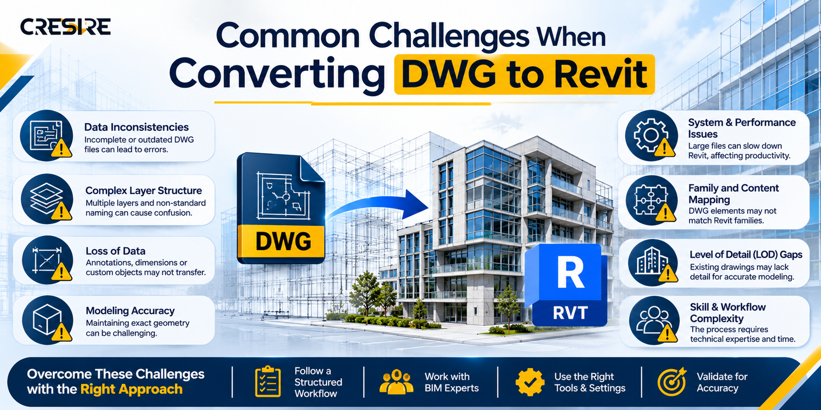
Although the workflow is straightforward in principle, actual projects can present several technical challenges.
1. Incorrect Drawing Units
A DWG file prepared in millimeters may be imported using incorrect units.
This can create substantial scaling errors in Revit.
Solution: Verify the original AutoCAD units and check at least one known dimension after importing the drawing.
2. Poorly Organized CAD Layers
Legacy DWG files may contain hundreds of layers, duplicate lines, unnecessary annotations, and outdated design information.
Solution: Clean the drawing in AutoCAD and import or link only the layers required for the modeling scope.
3. Inconsistent Architectural and Structural Drawings
Architectural and structural drawings may show different wall locations, column sizes, or opening dimensions.
Solution: Identify discrepancies and obtain clarification from the responsible design professional before finalizing the affected model elements.
4. Coordinate and Alignment Problems
Different consultants may prepare drawings using different origins or coordinate systems.
Solution: Establish a common project coordinate strategy and use verified reference points for alignment.
5. Excessive CAD Geometry in Revit
Importing several large DWG files can affect project performance and make views difficult to manage.
Solution: Clean the source files, link rather than unnecessarily import external drawings, and manage CAD visibility through view settings.
6. Missing Design Information
Some drawings may not include sufficient dimensions, sections, or construction details to support accurate modeling.
Solution: Create an information request list and confirm missing details with the design team. Do not invent dimensions or construction specifications.