Table of Contents
If you’ve ever stepped onto a construction site where the piping systems just don’t seem to fit together as they should, you know the kind of chaos that can unfold. You end up with expensive rework, delays in the schedule, and teams that are feeling pretty frustrated. This is precisely where pipe spool modeling in BIM makes a significant difference.
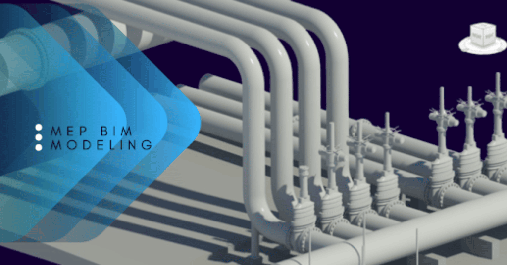
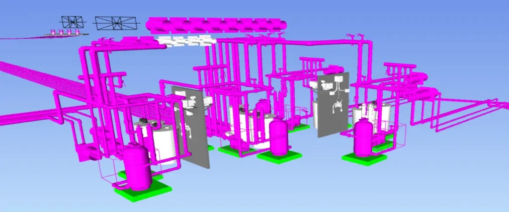
Pipe spool modeling is a methodical approach that revolutionizes how we prefabricate and install piping systems. By breaking down intricate piping networks into smaller, prefabricated sections known as spools, we’re ensuring precision in every weld, every joint, and every connection before anything even arrives at the construction site.
What Exactly is Pipe Spool Modeling?
Think of pipe spool modeling as crafting a detailed blueprint for prefabricated pipe assemblies. A pipe spool is essentially a pre-made section that brings together pipes, flanges, fittings, and valves into one cohesive unit. Instead of putting everything together on-site, these spools are created in controlled workshop settings and then shipped out for installation.
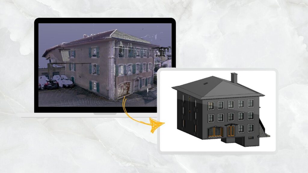
We work with intelligent 3D models that include every detail, including pipe dimensions, material specifications, weld locations, support systems, and assembly sequences, when we combine this process with BIM consulting services. Because of this digital-first strategy, installers receive components that fit together flawlessly, and fabricators receive precise instructions.
The BIM Workflow for Pipe Spool Modeling
Step 1: BIM Model Development
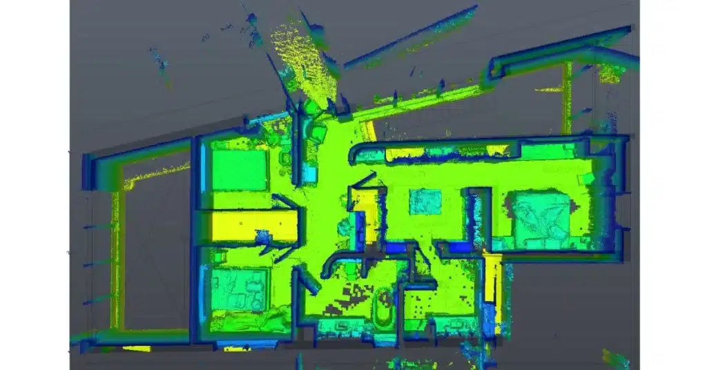
Start with coordinated 3D MEP models in platforms like Autodesk Revit. The piping systems are modeled with actual manufacturer specifications, ensuring that what you design is what you can actually build.
Step 2: Clash Detection and Coordination
Before any spooling begins, run comprehensive clash detection in BIM. Identify conflicts between piping, structural elements, ductwork, and electrical systems. Resolving these digitally saves enormous amounts of time and money compared to discovering them on-site.
Step 3: Spool Break Planning
Define where each spool begins and ends based on practical considerations: maximum transportable lengths, available lifting equipment, welding permissions on-site, and connection types. This is where engineering judgment meets fabrication reality.
Step 4: Generate Spool Drawings
Extract detailed isometric drawings from your 3D BIM models that include:
- Pipe lengths, diameters, and materials
- Fitting types and orientations
- Weld joint locations and specifications
- Support and hanger details
- Assembly sequences and installation instructions
Step 5: Bill of Materials and Fabrication Data
Generate accurate material takeoffs directly from the model using the quantity takeoff feature in Revit. This ensures purchasing teams order exactly what’s needed, and fabricators have complete material lists before starting work.
Step 6: Shop Fabrication
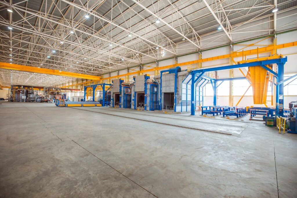
Send the spool drawings to fabrication shops where components are cut, welded, and assembled according to specifications. Quality control happens in controlled environments rather than cramped construction sites.
Step 7: Site Installation
Prefabricated spools arrive at the site ready for installation. Field teams connect pre-assembled units, dramatically reducing on-site labor and installation time.
Industry Standards for Pipe Spool Modeling
To guarantee uniformity and quality, professional pipe spool modeling adheres to established standards:
ASME B31.3: Process piping standards that specify fabrication specifications, design parameters, and material requirements
ISO 15926: International standard for interoperability and industrial data integration
Level of Development, or LOD: For fabrication models, LOD 400 is typically used, which means that components are modeled with precise quantities, assemblies, and fabrication details.
Project-specific requirements: Client requirements for material coding, welding techniques, drawing formats, and spool numbering
Successful fabrication workflows depend on the project team maintaining uniform modeling standards, according to Autodesk’s BIM for MEP guidelines.
How Pipe Spool Modeling in BIM Improves Fabrication Accuracy
Precision Manufacturing
When fabricators rely on detailed BIM-generated spool drawings, they’re not just making educated guesses about dimensions or assumptions in the field. Every single measurement is checked digitally. Research indicates that using machine-learning models in pipe spool fabrication can enhance delivery time predictions by cutting down estimation errors by 35%.
Reduced Material Waste
One contractor using automated spool generation reported a 30-35% reduction in material waste by connecting model data directly to cutting machines.
Faster Fabrication Cycles
Companies implementing BIM-driven spooling have documented productivity increases from 60 spool sheets per day to over 300. That’s a five-fold improvement in throughput, which translates directly to faster project delivery.
Fewer Site Installation Errors
Prefabricated spools arrive ready to install. Field teams aren’t interpreting vague drawings or making on-site modifications. Installation becomes an assembly process rather than a construction process, reducing errors and rework.
Enhanced Safety
Less on-site cutting, welding, and fitting means fewer safety hazards. Workers aren’t performing complex fabrication tasks in congested areas with overhead work happening simultaneously.
Better Quality Control
Workshop fabrication allows for systematic quality checks. Welds can be inspected thoroughly, dimensions verified, and non-destructive testing completed before anything leaves the shop.
Practical Implementation Tips
If you're looking to improve your pipe spool modeling process:
- Start with a pilot project: Test workflows on a smaller system before rolling out company-wide. Measure metrics like sheet production time and error rates to quantify improvements.
- Invest in training: Software tools are powerful but require expertise. Training your team pays dividends in productivity and accuracy.
- Establish shop standards: Define your spool breaking rules, maximum spool lengths, and connection preferences upfront. Consistency accelerates the entire process.
- Connect design to fabrication: The real power comes from integrated workflows. When your model drives cutting machines and tracking systems, efficiency multiplies.
- Monitor and optimize: Track key performance indicators like fabrication lead time, rework rates, and installation speed. Use this data to continuously refine your processes.
The ROI of Pipe Spool Modeling
- 40% increase in shop productivity reported across multiple implementations
- 90% faster spool sheet creation compared to manual methods
- 74% reduction in spooling time for some contractors
- 20% reduction in time spent communicating project status to stakeholders
Getting Started with Professional Pipe Spool Modeling
No matter if you’re tackling industrial facilities, commercial buildings, or infrastructure projects in the UK, USA, UAE, or Australia, adopting structured BIM workflows for pipe spool modeling is key to setting your projects up for success.
At CRESIRE, we pride ourselves on providing all-encompassing BIM solutions that connect design with fabrication. Our team knows the ins and outs of what it takes to move pipe spools from the model stage to installation. If you’re eager to boost your MEP fabrication accuracy and improve project efficiency, let’s chat about how effective spool modeling can revolutionize your workflows.
Contact our team to discuss and get a free quote for your project.
Frequently Asked Questions - FAQs
What's the difference between pipe spool drawings and fabrication drawings?
Pipe spool drawings are a specific type of fabrication drawing focused on prefabricated pipe assemblies. While fabrication drawings can include various construction details, spool drawings specifically show how pipe sections are broken down into manageable units with complete assembly information for shop fabrication.
Can small to medium-sized projects benefit from BIM pipe spool modeling?
Absolutely. While the setup requires initial investment, even smaller projects see benefits from reduced rework and faster installation.
How does pipe spool modeling integrate with existing project workflows?
Modern BIM platforms connect with project management, procurement, and fabrication systems. Data flows from design models to material orders, cutting instructions, and installation tracking without manual re-entry, creating an integrated digital thread through the project.
What Level of Development (LOD) is required for accurate spool modeling?
Fabrication-ready spool models typically require LOD 400, where components represent specific assemblies with accurate quantities, sizes, and installation details.
How long does it take to see ROI from implementing BIM-based spool modeling?
Most contractors report measurable improvements within the first project. However, full optimization usually takes 2-3 projects as teams refine their workflows and build confidence with new processes.

Devashish is Founder/Director at Cresire where he leads BIM services. He holds a bachelor’s degree in Civil Engineering from the University of Sheffield and an MSc in Construction Project Management from The University of the West of England. His vision behind CRESIRE is to provide BIM services, adhering to best practices and procedures, to global customers, helping customers to save extensive production costs and overruns.
Our Recent Projects on BIM Services

Related Posts