Discover CAD electrical circuit breaker diagrams including single line, schematic, and wiring, panel drawings from concept to design. Get a FREE Quote for your project.

Introduction
Regarding Architecture, Engineering, and Construction (AEC), accurate CAD Electrical Circuit Breaker Diagrams are essential.
Every step of the process, from planning to execution, requires careful consideration of even the smallest details.
In this blog post, we will discuss the importance of Electrical CAD Drawings of Circuit Break, including their various types, uses, and benefits of partnering with CRESIRE for developing AutoCAD Electrical Circuit Breaker Diagrams using conceptual sketches and design.
Understanding Electrical Circuit Breaker Diagrams
Electrical Circuit Breaker Diagrams are important for power distribution systems, as they help ensure safety, efficiency, and compliance with regulations.
The diagrams show how circuits are laid out, detailing connections, components, and protective devices such as circuit breakers.
There are different types of Electrical Drawing of Circuit Breaker, including:
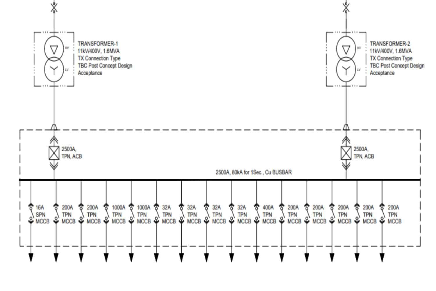
1. Single Line Diagrams (SLDs)
Single Line Diagrams (SLDs) offer a basic visual of how electricity moves from the power source to different devices using components like transformers, circuit breakers, and switches. These diagrams make it easier to understand the setup of the electrical system.
2. Circuit Breaker Schematic Diagram
Circuit Breaker Schematic Diagram offer a detailed portrayal of circuitry, showcasing the interconnections between components using standardized symbols.
It helps in troubleshooting, maintenance, and modification of electrical systems by presenting a clear depiction of circuit paths and functionalities.
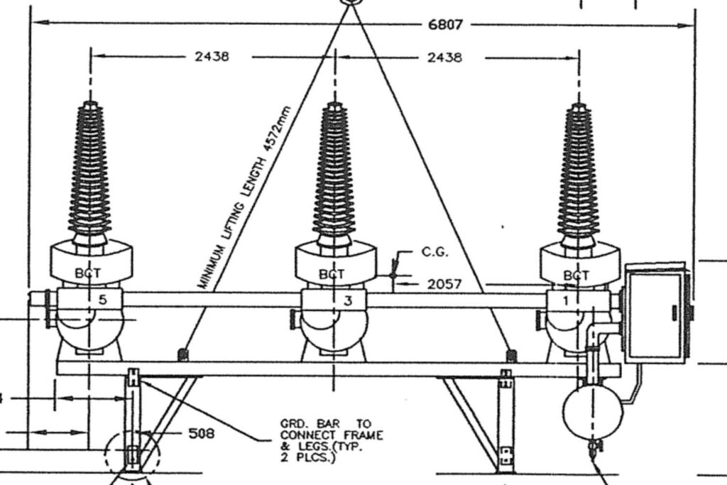
3. Circuit Breaker Wiring Diagram
Circuit Breaker Wiring Diagram focus on the physical layout of electrical components, illustrating the arrangement of wires, terminals, and connections within a system.
The Circuit Breaker Diagram Wiring are indispensable during installation and wiring tasks, guiding electricians to ensure accurate assembly and connectivity.
Serving Every Continent

USA & Canada
UK & Europe
Benefits of Drawing CAD Electrical Circuit Breaker Diagrams from Concept
Accurate electrical circuit breaker diagrams offer a multitude of benefits, including:
1. Enhanced Safety
Clear and comprehensive diagrams mitigate the risk of electrical hazards by facilitating proper installation, maintenance, and troubleshooting procedures.
2. Efficiency in Design and Construction
Well-developed diagrams streamline the design and construction process, minimizing errors, rework, and delays.
3. Compliance Assurance
Compliance with regulatory standards and building codes is ensured through precise documentation of electrical systems, minimizing the potential for non-compliance penalties and safety violations.
4. Cost Savings
An effective design and execution strategy helps minimize waste, cut labor expenses, and speed up project schedules, leading to substantial savings for professionals in the Architecture, Engineering, and Construction (AEC) industries.
Partnering with CRESIRE for CAD Electrical Circuit Breaker Diagrams
CRESIRE is a BIM Consulting Company, offering electrical circuit breaker CAD drafting services.
Partnering with CRESIRE to develop CAD electrical circuit breaker diagrams presents several advantages:
1. Tailored Solutions
CRESIRE collaborates closely with clients to understand their specific requirements, delivering customized solutions tailored to their project objectives and preferences.
2. Latest Technology
Leveraging advanced CAD software and BIM tools, CRESIRE ensures precision, accuracy, and efficiency in the development of electrical circuit break diagrams.
3. Timely Delivery
With a commitment to meeting project deadlines, CRESIRE ensures prompt delivery of CAD electrical circuit breaker diagrams, facilitating seamless integration into AEC workflows.
Conclusion
In the ever-changing world of Architecture, Engineering, and Construction, having precise and carefully designed AutoCAD Electrical Circuit Breaker Diagrams is crucial.
These diagrams are essential for Architects, Engineers, and Construction workers from the initial planning stages to the final execution of a project.
By collaborating with CRESIRE, professionals in the AEC industry can access the latest drafting technology and specialized knowledge to simplify the creation of CAD electrical circuit breaker drawings using conceptual sketches.
This streamlined process not only improves safety and efficiency but also ensures project compliance with regulations.
Related Posts
Related Posts
Share Via
Tags

Devashish Sharma
Devashish is Founder/Director at Cresire where he leads BIM services. He holds a bachelor’s degree in Civil Engineering from the University of Sheffield and an MSc in Construction Project Management from The University of the West of England. His vision behind CRESIRE is to provide BIM services, adhering to best practices and procedures, to global customers, helping customers to save extensive production costs and overruns.


