MEP BIM Modeling Using CAD Drawings & Laser Scan Data

Project Scope

MEP BIM Modeling from CAD Drawings & Scan Data

Building Type

Industrial

Client

Construction Company

Inputs

2D CAD Drawings, Laser Scan / Point Cloud Data, Reference Documents

Deliverables

Revit MEP Model

Industry

Engineering

Timeline

2 week

Location

USA

Scope of Work

HVAC systems, ductwork, pipework, plumbing, equipment and other visible MEP elements as defined in the project scope.

About Projects

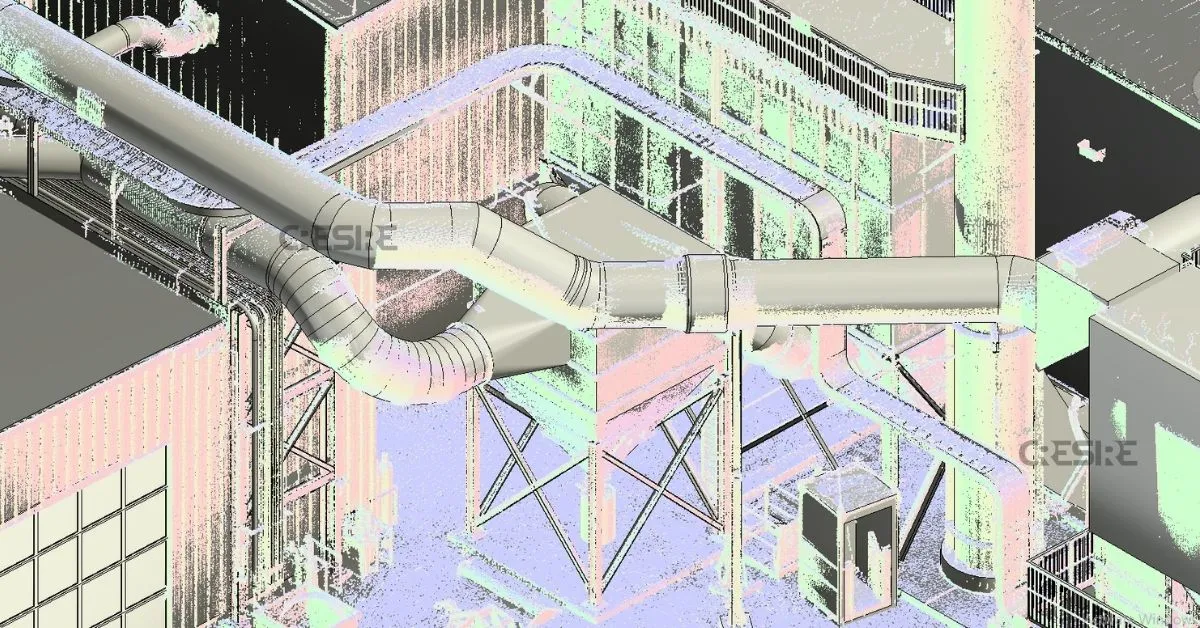
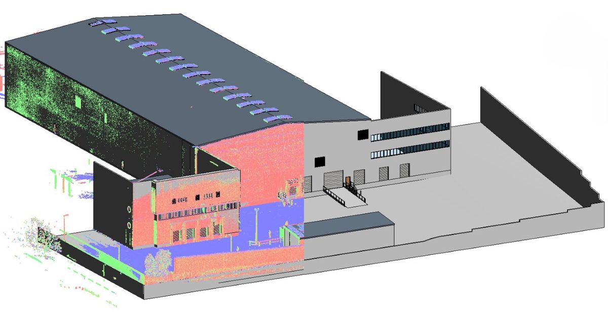
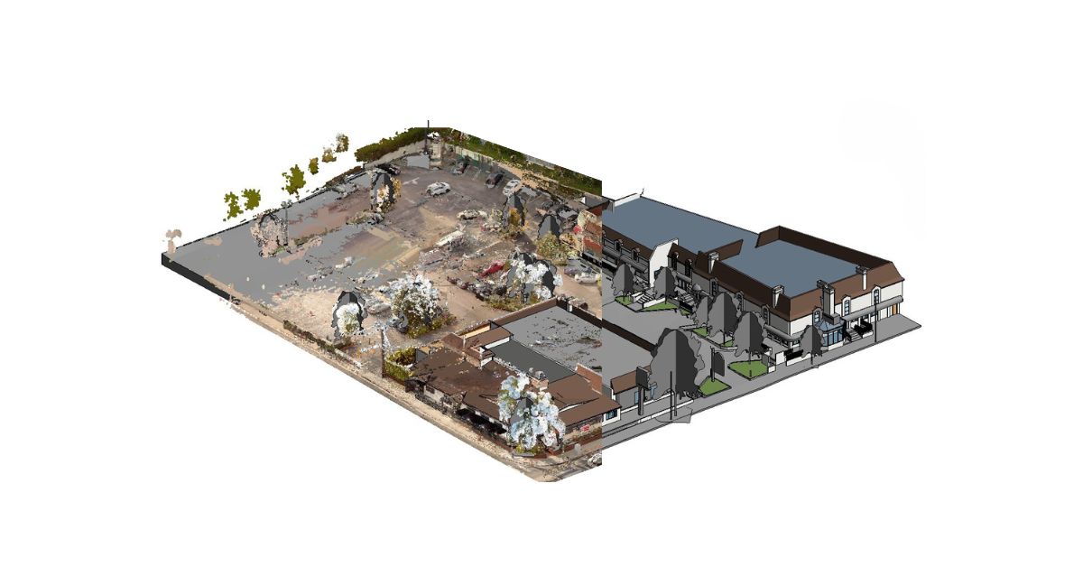
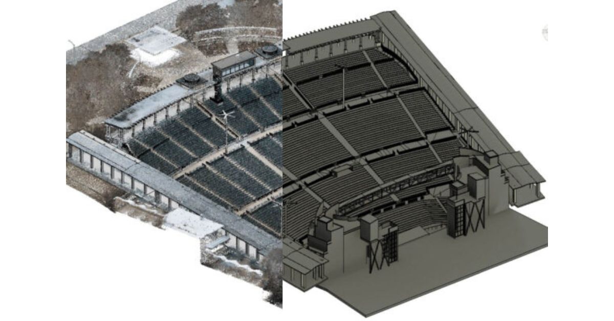
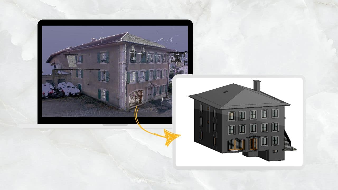
CRESIRE delivered MEP BIM modeling for an existing building using a combination of 2D CAD drawings and laser scan data. The objective was to develop a coordinated Revit MEP model that represented the available design information while incorporating verified existing site conditions captured through scanning.

Using both sources was important because the CAD drawings provided the design and documentation reference, while the laser scan data helped the team understand the actual spatial conditions of the building.

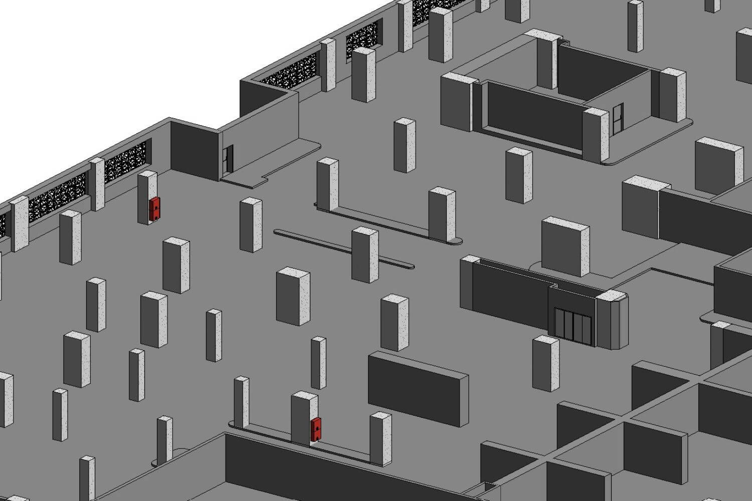
The resulting BIM model provided a structured digital environment for MEP coordination, design development, clash review and project planning.

Software We Used

autodesk-recap-pro-uk

Solutions

CRESIRE combined CAD drawings with point cloud data to develop a more reliable understanding of the existing MEP conditions. CAD provided documented layouts and dimensions, while the laser scan helped verify the actual spatial relationships between MEP systems and the building.

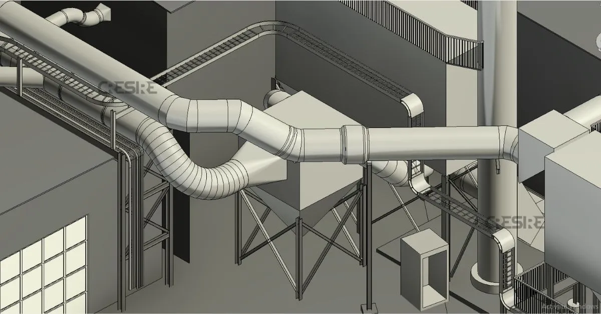
The required MEP systems were modeled natively in Revit based on the agreed scope and LOD. CAD & Point Cloud Review → Revit Setup → MEP Modeling → Verification → Coordination → QA/QC → Final Model Where scan data provided clearer evidence of existing conditions, it was used to inform the model in line with project requirements.

The completed model brought MEP systems into a common BIM environment, allowing the team to review relationships between:

  • HVAC and ductwork
  • Pipework and plumbing
  • MEP equipment
  • Architectural and structural elements
This provided a stronger basis for coordination and design review before construction.

Results

By combining CAD drawings with laser scan data, CRESIRE developed a structured MEP BIM model that helped the project team:

  • Visualize existing MEP systems in 3D
  • Understand spatial relationships between services
  • Review MEP routing against architectural and structural conditions
  • Identify potential coordination issues
  • Reduce reliance on disconnected 2D documentation

MEP projects involving existing buildings often require more than one source of information. CAD drawings may explain how a system was documented, while laser scanning can provide valuable insight into what is physically present on site. When these sources are interpreted together, they can provide a stronger foundation for MEP BIM modeling. For this project, CRESIRE combined CAD documentation, laser scan data and Revit-based MEP modeling to create a coordinated digital representation of the available existing conditions. The resulting BIM model provided the project team with a practical foundation for MEP coordination, design development and future project planning.

Final thoughts

24-HOUR QUOTE RESPONSE

Start Your Projects Today

enquiry@cresireconsulting.com

NDA available

Scroll to Top